Difference between revisions of "Wiring"
| (12 intermediate revisions by 2 users not shown) | |||
| Line 30: | Line 30: | ||
Neverthless you can also completely disable the unit' operation so that the control will be same as without the system. Then it can be anytime re-enabled during the flight.</translate> | Neverthless you can also completely disable the unit' operation so that the control will be same as without the system. Then it can be anytime re-enabled during the flight.</translate> | ||
| + | == <translate>SERVO CONNECTION</translate> == | ||
| + | {| style="color:black; background-color:Lavender;width:75%;" | ||
| + | |<span style="color:red">'''μSpirit'''</span> | ||
| + | |- | ||
| + | |''CH1'' – <translate> | ||
| + | <!--T:84--> | ||
| + | 1st Aileron / Elevon servo</translate> | ||
| + | |- | ||
| + | |''CH2'' – <translate> | ||
| + | <!--T:85--> | ||
| + | Elevator servo</translate> | ||
| + | |- | ||
| + | |''CH3'' – <translate> | ||
| + | <!--T:86--> | ||
| + | 2nd Aileron / Elevon servo</translate> | ||
| + | |- | ||
| + | |''CH4'' – <translate> | ||
| + | <!--T:87--> | ||
| + | Rudder servo</translate> | ||
| + | |} | ||
| + | <p></p> | ||
{| style="color:black; background-color:Lavender; width:75%;" | {| style="color:black; background-color:Lavender; width:75%;" | ||
|<span style="color:red">'''Spirit'''</span> | |<span style="color:red">'''Spirit'''</span> | ||
| Line 46: | Line 67: | ||
Rudder servo</translate> | Rudder servo</translate> | ||
|} | |} | ||
| − | + | <p></p> | |
| − | + | ||
{| style="color:black; background-color:Lavender; width:75%;" | {| style="color:black; background-color:Lavender; width:75%;" | ||
|<span style="color:red">'''Spirit Pro'''</span> | |<span style="color:red">'''Spirit Pro'''</span> | ||
| Line 68: | Line 88: | ||
|- | |- | ||
|''CH0'' – <translate><!--T:22--> | |''CH0'' – <translate><!--T:22--> | ||
| − | Auxiliary (optional) servo</translate> | + | Auxiliary/2nd Elevator (optional) servo</translate> |
|} | |} | ||
| Line 79: | Line 99: | ||
== <translate><!--T:25--> | == <translate><!--T:25--> | ||
CONNECTION OF STANDARD RECEIVER (PWM)</translate> == | CONNECTION OF STANDARD RECEIVER (PWM)</translate> == | ||
| + | |||
| + | [[File:MPWM.png|400px|center]] | ||
| + | |||
| + | <center> | ||
| + | <span style="color:red">'''''μSpirit'''''</span>''<translate> | ||
| + | <!--T:88--> | ||
| + | – receiver type: PWM</translate>'' | ||
| + | </center> | ||
[[File:pwms.png|class=halfwidth|center]] | [[File:pwms.png|class=halfwidth|center]] | ||
| Line 103: | Line 131: | ||
<!--T:30--> | <!--T:30--> | ||
| − | The easiest way you can start is to connect RUD with Rudder output in the receiver. Then continue with AUX which should be connected to the Gyro Gain channel output. Next, connect the Aileron, Elevator channels and optionally Flaps channel. If you are not sure whether you have the correct output or not, you can plug in one servo and power the unit to verify that your connection is correct. This can be repeated for each servo. The diagnostics tab is very helpful too.</translate> | + | The easiest way you can start is to connect RUD with Rudder output in the receiver. Then continue with AUX which should be connected to the Gyro Gain channel output. Next, connect the Aileron (AIL pin), Elevator (ELE pin) channels and optionally Flaps channel (PIT pin). If you are not sure whether you have the correct output or not, you can plug in one servo and power the unit to verify that your connection is correct. This can be repeated for each servo. The diagnostics tab is very helpful too.</translate> |
| − | + | ||
| − | + | ||
| − | + | ||
{{Info|'''Spirit Pro'''<br /><translate><!--T:31--> | {{Info|'''Spirit Pro'''<br /><translate><!--T:31--> | ||
| Line 120: | Line 145: | ||
== <translate><!--T:33--> | == <translate><!--T:33--> | ||
CONNECTION OF SPEKTRUM DSM2/X SATELLITE</translate> == | CONNECTION OF SPEKTRUM DSM2/X SATELLITE</translate> == | ||
| + | |||
| + | [[File:MSatellite.png|400px|center]] | ||
| + | |||
| + | <center> | ||
| + | <span style="color:red">'''''μSpirit'''''</span>''<translate> | ||
| + | <!--T:89--> | ||
| + | – receiver type: Spektrum DSM2/X</translate>'' | ||
| + | </center> | ||
| Line 147: | Line 180: | ||
To use both, two satellites and an external BEC, be sure to use a Y-harness made from large gauge wire to supply the high current that is needed.</translate> | To use both, two satellites and an external BEC, be sure to use a Y-harness made from large gauge wire to supply the high current that is needed.</translate> | ||
}} | }} | ||
| − | + | <p></p> | |
| − | + | ||
{{Info|'''Spirit Pro'''<br /><translate> | {{Info|'''Spirit Pro'''<br /><translate> | ||
<!--T:39--> | <!--T:39--> | ||
| Line 165: | Line 197: | ||
== <translate><!--T:42--> | == <translate><!--T:42--> | ||
CONNECTION OF FUTABA S-BUS RECEIVER</translate> == | CONNECTION OF FUTABA S-BUS RECEIVER</translate> == | ||
| + | |||
| + | [[File:MS-BUS.png|400px|center]] | ||
| + | |||
| + | <center> | ||
| + | <span style="color:red">'''''μSpirit'''''</span>''<translate> | ||
| + | <!--T:90--> | ||
| + | – receiver type: Futaba S-BUS</translate>'' | ||
| + | </center> | ||
| Line 186: | Line 226: | ||
When using S-BUS it is necessary to use an inverter that replaces the cable between the receiver and the Spirit unit's RUD port. This inverter cable can be purchased separately. | When using S-BUS it is necessary to use an inverter that replaces the cable between the receiver and the Spirit unit's RUD port. This inverter cable can be purchased separately. | ||
The inverter cable have to be connected in the way, that longer end is directed to the unit and shorter to the receiver.</translate>}} | The inverter cable have to be connected in the way, that longer end is directed to the unit and shorter to the receiver.</translate>}} | ||
| − | + | <p></p> | |
| − | + | ||
{{Info|'''Spirit Pro'''<br /><translate><!--T:46--> | {{Info|'''Spirit Pro'''<br /><translate><!--T:46--> | ||
Connect the receiver with the unit by normal patch cable to the RUD port. | Connect the receiver with the unit by normal patch cable to the RUD port. | ||
| Line 207: | Line 246: | ||
== <translate><!--T:50--> | == <translate><!--T:50--> | ||
CONNECTION OF PPM RECEIVER</translate> == | CONNECTION OF PPM RECEIVER</translate> == | ||
| + | |||
| + | [[File:MPPM.png|400px|center]] | ||
| + | |||
| + | <center> | ||
| + | <span style="color:red">'''''μSpirit'''''</span>''<translate> | ||
| + | <!--T:91--> | ||
| + | – receiver type: PPM</translate>'' | ||
| + | </center> | ||
| Line 241: | Line 288: | ||
== <translate><!--T:57--> | == <translate><!--T:57--> | ||
CONNECTION OF JETI EX BUS RECEIVER</translate> == | CONNECTION OF JETI EX BUS RECEIVER</translate> == | ||
| + | |||
| + | [[File:MEX-BUS.png|400px|center]] | ||
| + | |||
| + | <center> | ||
| + | <span style="color:red">'''''μSpirit'''''</span>''<translate> | ||
| + | <!--T:92--> | ||
| + | – receiver type: Jeti EX Bus</translate>'' | ||
| + | </center> | ||
| Line 268: | Line 323: | ||
'''<translate><!--T:65--> | '''<translate><!--T:65--> | ||
| − | A special cable is needed to enable this communication.</translate>''' | + | A special cable is needed to enable this communication. Signal wire (Orange) is connected to the AIL pin, while power wires (Red and Brown) are connected to the RUD port in the unit. For JETI REX receivers, end of the special cable is connected to the EX1 or EX2 (depending on the receiver configuration). For EX receivers, please use EXT port.</translate>''' |
'''<translate><!--T:66--> | '''<translate><!--T:66--> | ||
| Line 277: | Line 332: | ||
== <translate><!--T:67--> | == <translate><!--T:67--> | ||
CONNECTION OF SRXL/SUMD RECEIVER</translate> == | CONNECTION OF SRXL/SUMD RECEIVER</translate> == | ||
| + | |||
| + | [[File:MSRXL.png|400px|center]] | ||
| + | |||
| + | <center> | ||
| + | <span style="color:red">'''''μSpirit'''''</span>''<translate> | ||
| + | <!--T:93--> | ||
| + | – receiver type: SRXL/SUMD</translate>'' | ||
| + | </center> | ||
| Line 295: | Line 358: | ||
| − | {{Info|[[File:info.png|18px]] | + | {{Info|[[File:info.png|18px|]] |
<translate><!--T:71--> | <translate><!--T:71--> | ||
Connection to a BEC is optional. For models with standard size servos it is recommended to use dual power supply cables due to the increased power consumption. That means besides the communication cable, an additional power supply cable should be connected to the AUX port. | Connection to a BEC is optional. For models with standard size servos it is recommended to use dual power supply cables due to the increased power consumption. That means besides the communication cable, an additional power supply cable should be connected to the AUX port. | ||
This protocol family can work with a wide range of receivers. | This protocol family can work with a wide range of receivers. | ||
| − | Thus you can use Multiplex SRXL, BeastX SRXL, | + | Thus you can use Multiplex SRXL, BeastX SRXL, Graupner SUMD, Jeti UDI, Spektrum SRXL and more.</translate> |
}} | }} | ||
| Line 313: | Line 376: | ||
== <translate><!--T:74--> | == <translate><!--T:74--> | ||
CONNECTOR ORIENTATION</translate> == | CONNECTOR ORIENTATION</translate> == | ||
| + | |||
| + | === μSpirit === | ||
| + | {{Quote|<translate> | ||
| + | <!--T:82--> | ||
| + | Pin layout of the '''JST-ZH(R) connectors is different''' from standard Servo connectors. BROWN (Middle) wire is GND pin. ORANGE wire is SIGNAL pin. RED wire is +5V (BEC voltage). By using '''JST-Servo''' cables you can connect a classic Servos and all Spirit peripherals to the μSpirit even with Servo connectors.</translate>}} | ||
| + | |||
| + | [[File:uspirit-polarity.png|280px|center]] | ||
| + | |||
| + | === Spirit and Spirit Pro === | ||
<translate> | <translate> | ||
| − | <!--T: | + | <!--T:83--> |
All cables connected to the unit must be oriented so that the signal wire (Lightest color wire) is closer to the connector pin label, towards the center of the unit. This orients the negative (darkest color wire) toward the edge of the unit.</translate> | All cables connected to the unit must be oriented so that the signal wire (Lightest color wire) is closer to the connector pin label, towards the center of the unit. This orients the negative (darkest color wire) toward the edge of the unit.</translate> | ||
| + | |||
| + | [[File:spiritpro-polarity.png|300px|center]] | ||
Latest revision as of 10:23, 13 June 2018
Spirit can be used as a gyro, stabilisation and rescue system. Wiring to the unit depends on the type of receiver used.
Spirit is pre-programmed to 1520µs servo neutral impulse and 50Hz frequency – please ensure you have the correct servo parameters selected as specified by your servo manufacturer.
Some connectors have non-standard dimensions that could interfere with neighboring connectors after plugging in the unit. As a solution, we recommend replacing these connectors with JR or Futaba type.
Never plug a connector for powering the unit into the SYS or ELE/PIT/AIL positions or you may risk damaging the unit.
Contents
1 GYRO
R/C models can take advantage of the full capabilities of the Spirit unit. The Spirit will stabilize the model on all axes and also make it less affected by wind or other unfavorable conditions. When properly set up, flight characteristics should be more stable which will give you the confidence to carry out even the most challenging maneuvers.
Neverthless you can also completely disable the unit' operation so that the control will be same as without the system. Then it can be anytime re-enabled during the flight.
2 SERVO CONNECTION
| μSpirit |
| CH1 – 1st Aileron / Elevon servo |
| CH2 – Elevator servo |
| CH3 – 2nd Aileron / Elevon servo |
| CH4 – Rudder servo |
| Spirit |
| CH1 – 1st Aileron / Elevon servo |
| CH2 – Elevator servo |
| CH3 – 2nd Aileron / Elevon servo |
| CH4 – Rudder servo |
| Spirit Pro |
| CH1 – 1st Aileron / Elevon servo |
| CH2 – Elevator servo |
| CH3 – 2nd Aileron / Elevon servo |
| CH4 – Rudder servo |
| CH0 – Auxiliary/2nd Elevator (optional) servo |
Flying wing (Delta) models should use only CH1 and CH3 servo outputs.
3 CONNECTION OF STANDARD RECEIVER (PWM)
μSpirit – receiver type: PWM
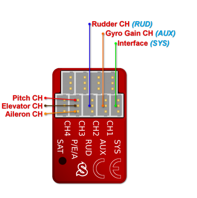
Spirit – receiver type: PWM
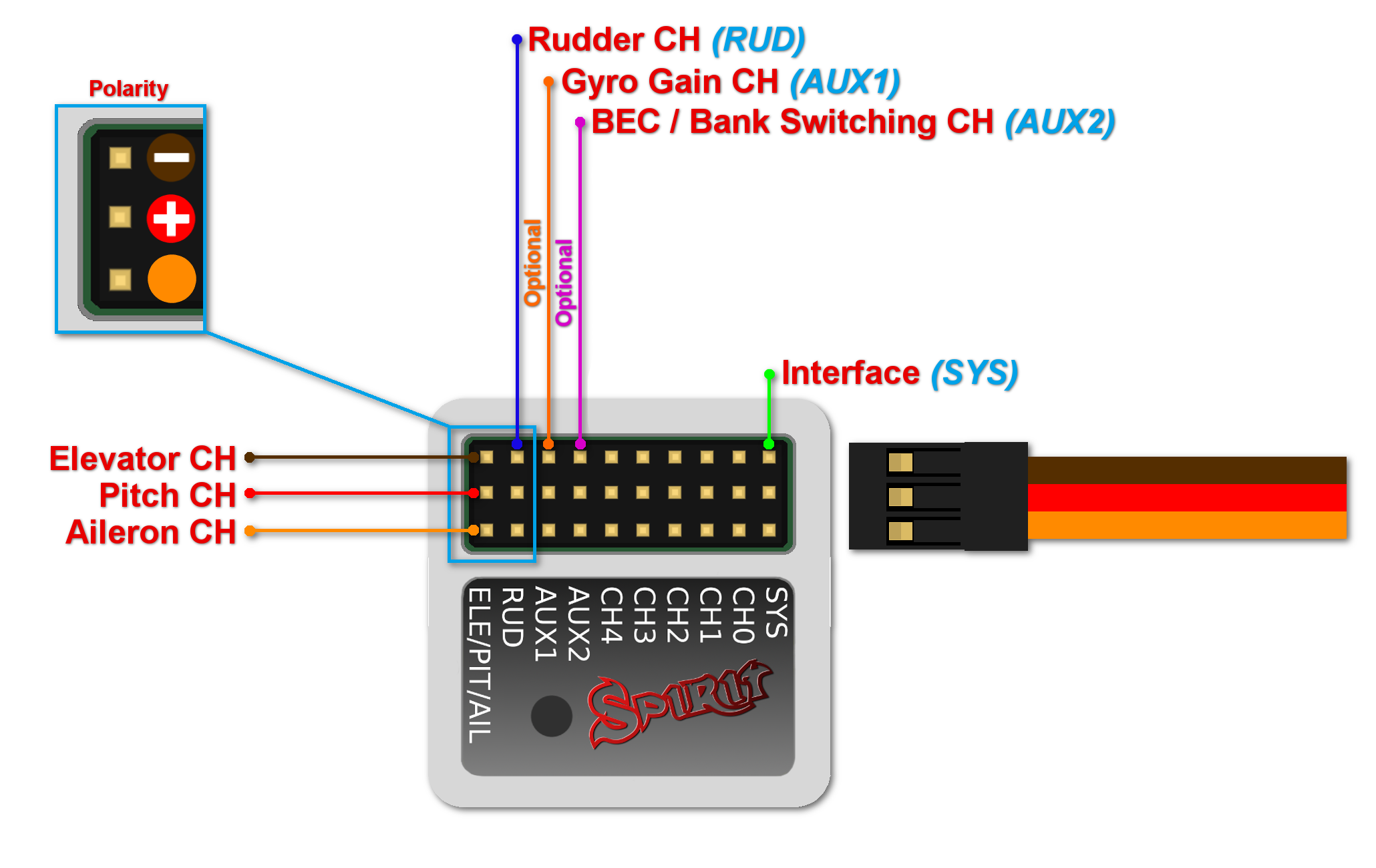
Spirit Pro – receiver type: PWM
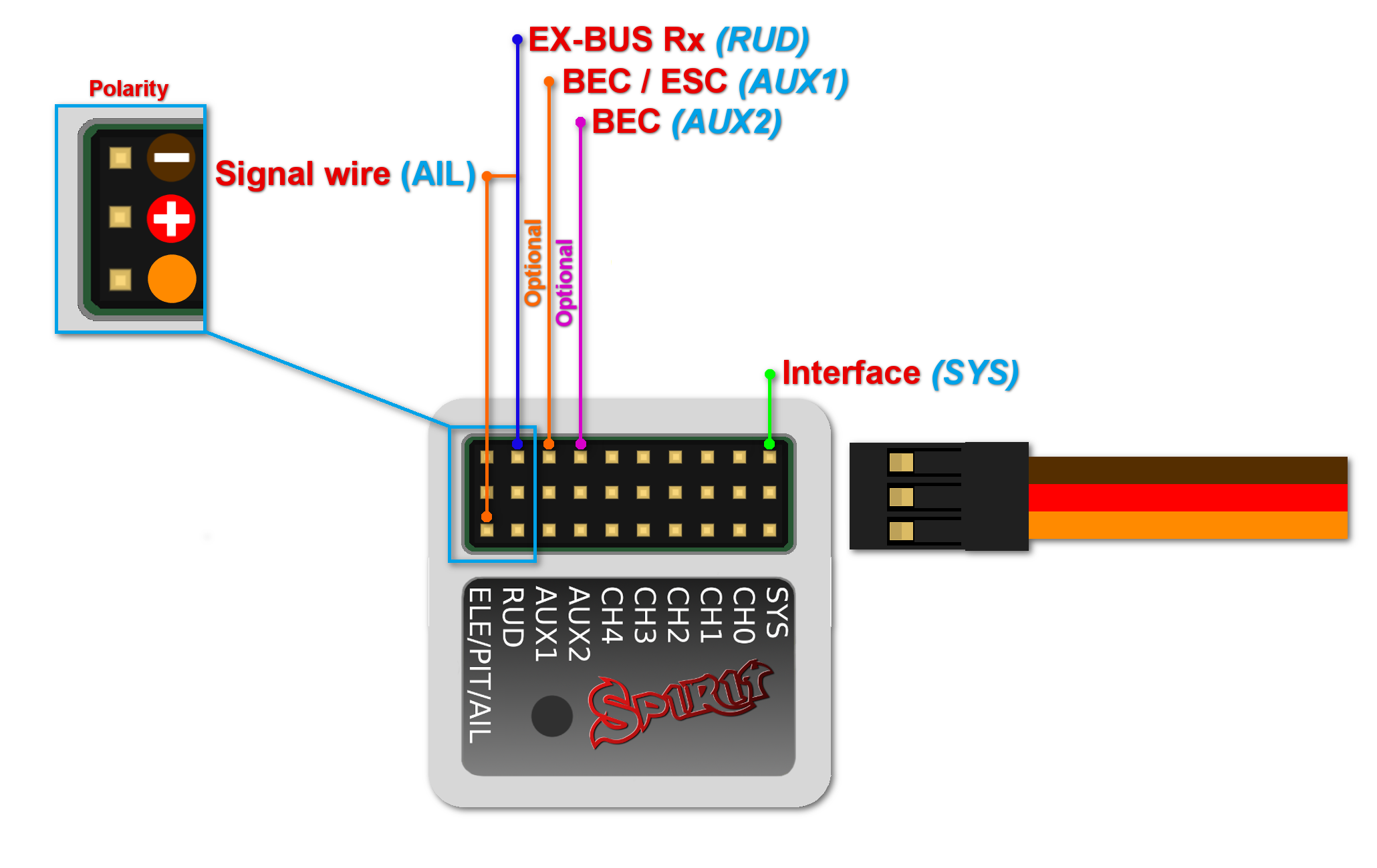
For standard receivers it is necessary to use two normal and one special cable. Three connectors from the special cable should be plugged into the receiver and the end of this cable to the unit.
The unit is powered by two cables from the receiver connected to AUX and RUD positions. The Throttle cable should be connected to the receiver as well.
The easiest way you can start is to connect RUD with Rudder output in the receiver. Then continue with AUX which should be connected to the Gyro Gain channel output. Next, connect the Aileron (AIL pin), Elevator (ELE pin) channels and optionally Flaps channel (PIT pin). If you are not sure whether you have the correct output or not, you can plug in one servo and power the unit to verify that your connection is correct. This can be repeated for each servo. The diagnostics tab is very helpful too.
Spirit Pro
The unit is able to control Bank Switching by 7th channel of the receiver. Connect the cable to the AUX2 port and allow Bank Switching in the software.
Never plug a connector for powering the unit to SYS or ELE/PIT/AIL ports.
4 CONNECTION OF SPEKTRUM DSM2/X SATELLITE
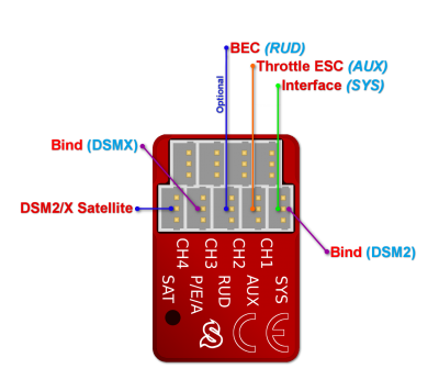
μSpirit – receiver type: Spektrum DSM2/X
Spirit – receiver type: Spektrum DSM2/X
Spirit Pro – receiver type: Spektrum DSM2/X
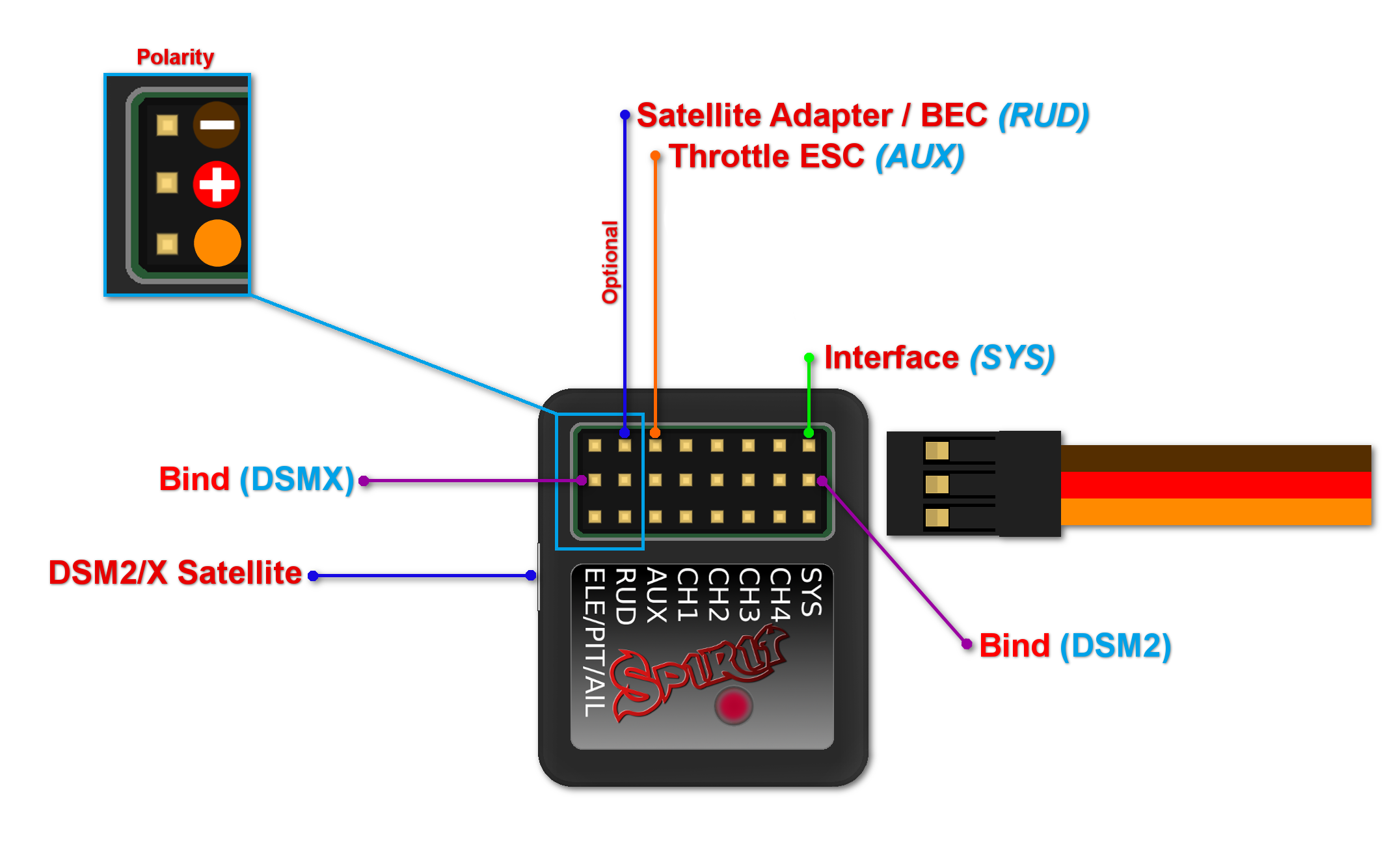
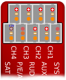
Connection to a BEC is optional. If the model is powered by an external BEC, this must be connected to the RUD port. Also the power lead from the ESCs internal BEC must be disconnected.
Spirit
A second satellite can be connected, but this can only be achieved via a special adapter connected to the RUD port. This adapter can be purchased separately. Before satellites can be used they must be bound to your transmitter, taking into account any failsafes that need to be set. To use both, two satellites and an external BEC, be sure to use a Y-harness made from large gauge wire to supply the high current that is needed.
Spirit Pro
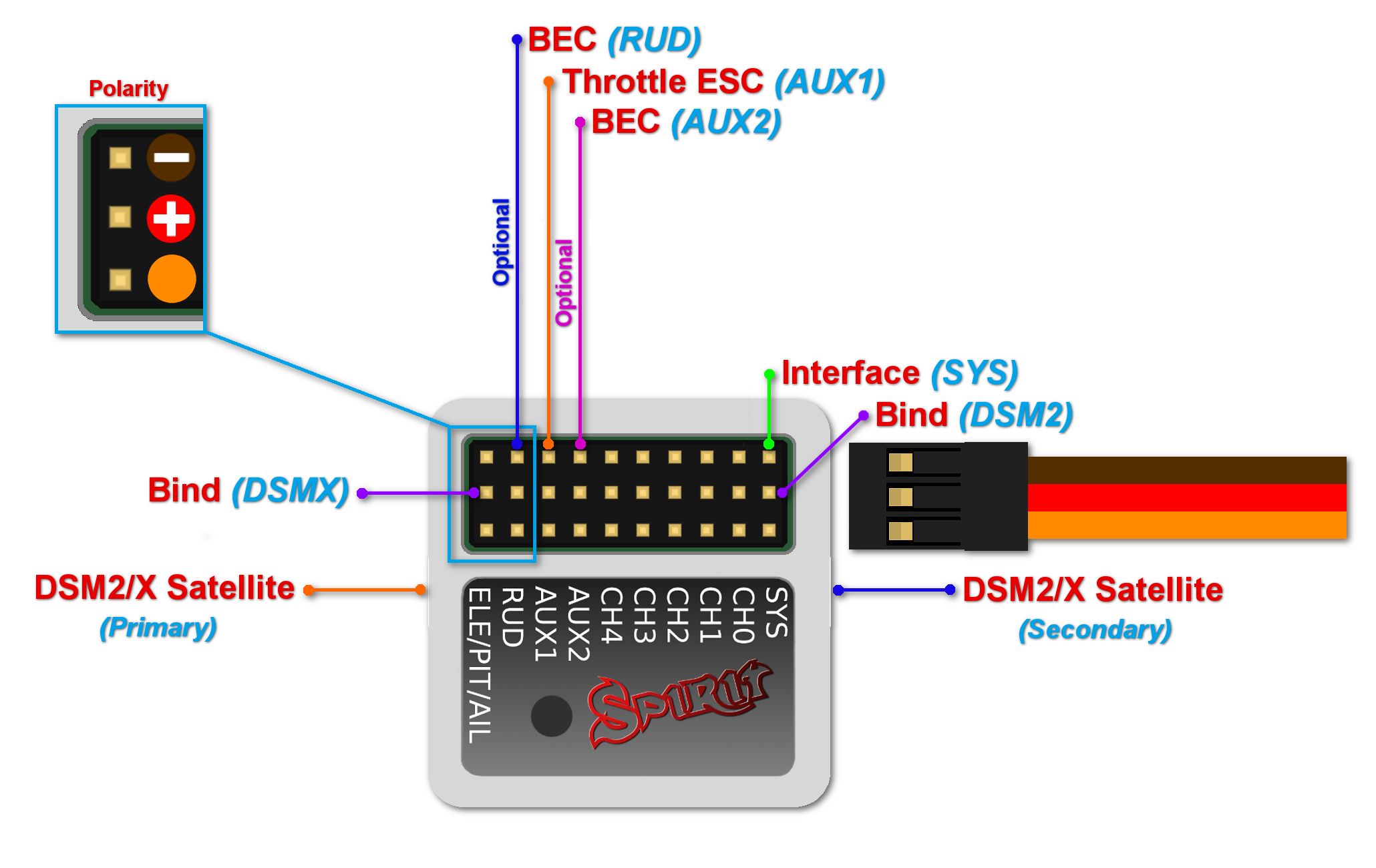
The Pro version allows you to connect two satellites directly to the unit. If you want to use only one satellite, you have to use the Primary connector.
To bind the satellites, insert a bind plug in the SYS port for DSM2 satellites or the ELE/PIT/AIL port for DSMX satellites. Power cycling the Spirit start the bind process. Once successfully bound, the STATUS LED will go out and the satellite LED will come on.
If the second satellite fails to bind, swap the satellites and repeat the bind process.
Be sure Receiver type in the software is configured to Spektrum DSM2/X or else binding process will not work. Never plug a connector for powering the unit to SYS or ELE/PIT/AIL positions.
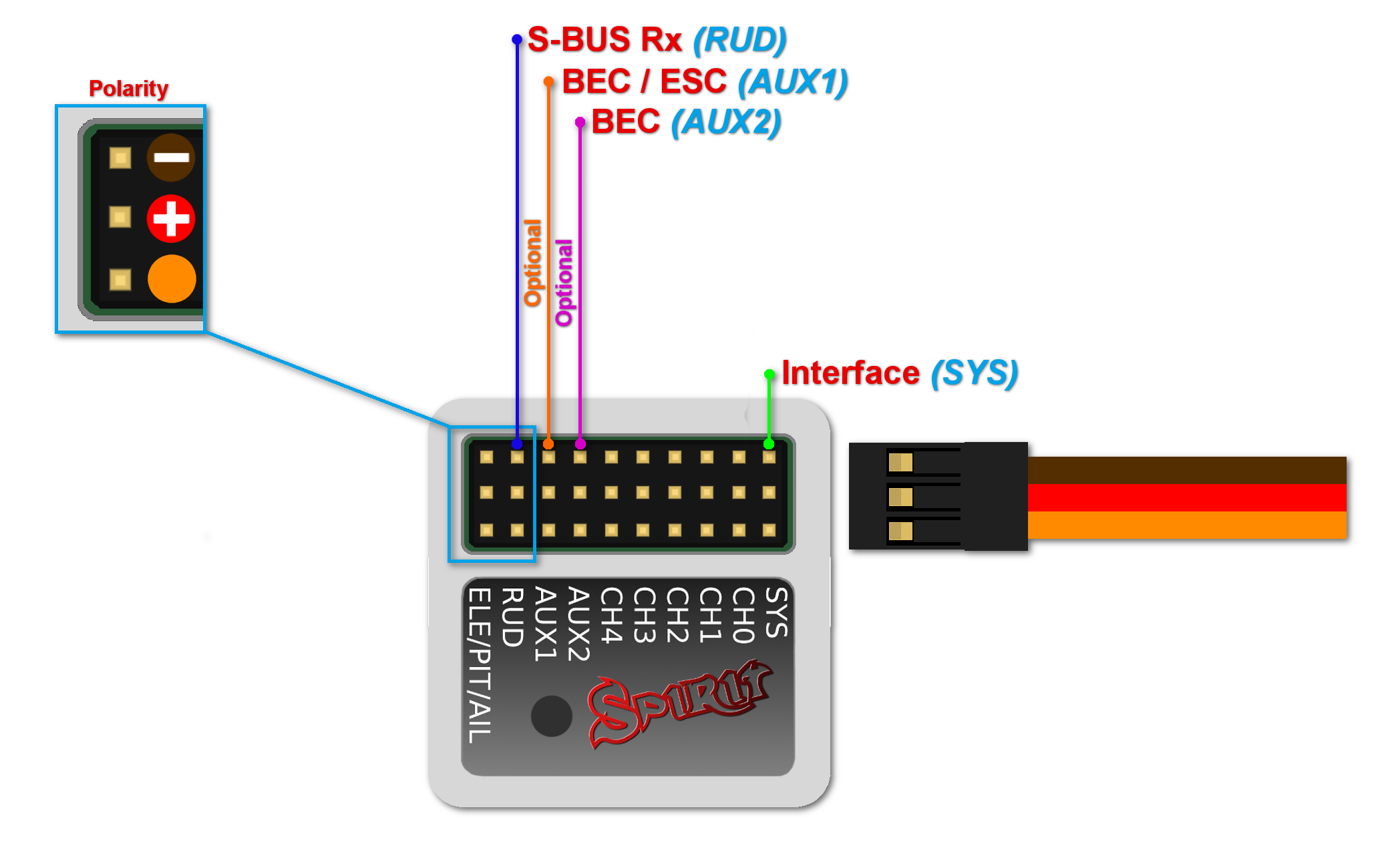
5 CONNECTION OF FUTABA S-BUS RECEIVER
μSpirit – receiver type: Futaba S-BUS
Spirit – receiver type: Futaba S-BUS
Spirit Pro – receiver type: Futaba S-BUS
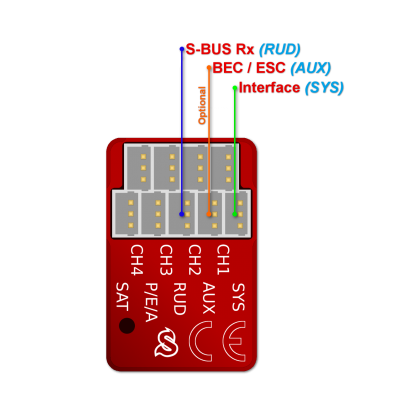
Spirit
When using S-BUS it is necessary to use an inverter that replaces the cable between the receiver and the Spirit unit's RUD port. This inverter cable can be purchased separately. The inverter cable have to be connected in the way, that longer end is directed to the unit and shorter to the receiver.
Spirit Pro
Connect the receiver with the unit by normal patch cable to the RUD port. You can use cable that is included in the package.
Connection to a BEC is optional. For models with standard size servos it is recommended to use dual power supply cables due to the increased power consumption. That means besides the S-BUS cable, an additional power supply cable should be connected to the AUX port.
When using this type of receiver you can connect the throttle cable directly to the receiver. Alternatively, you can assign the throttle channel in the software and use the AUX as throttle output from the unit.
Never plug a connector for powering the unit to SYS or ELE/PIT/AIL ports.
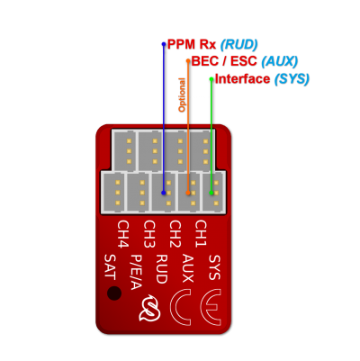
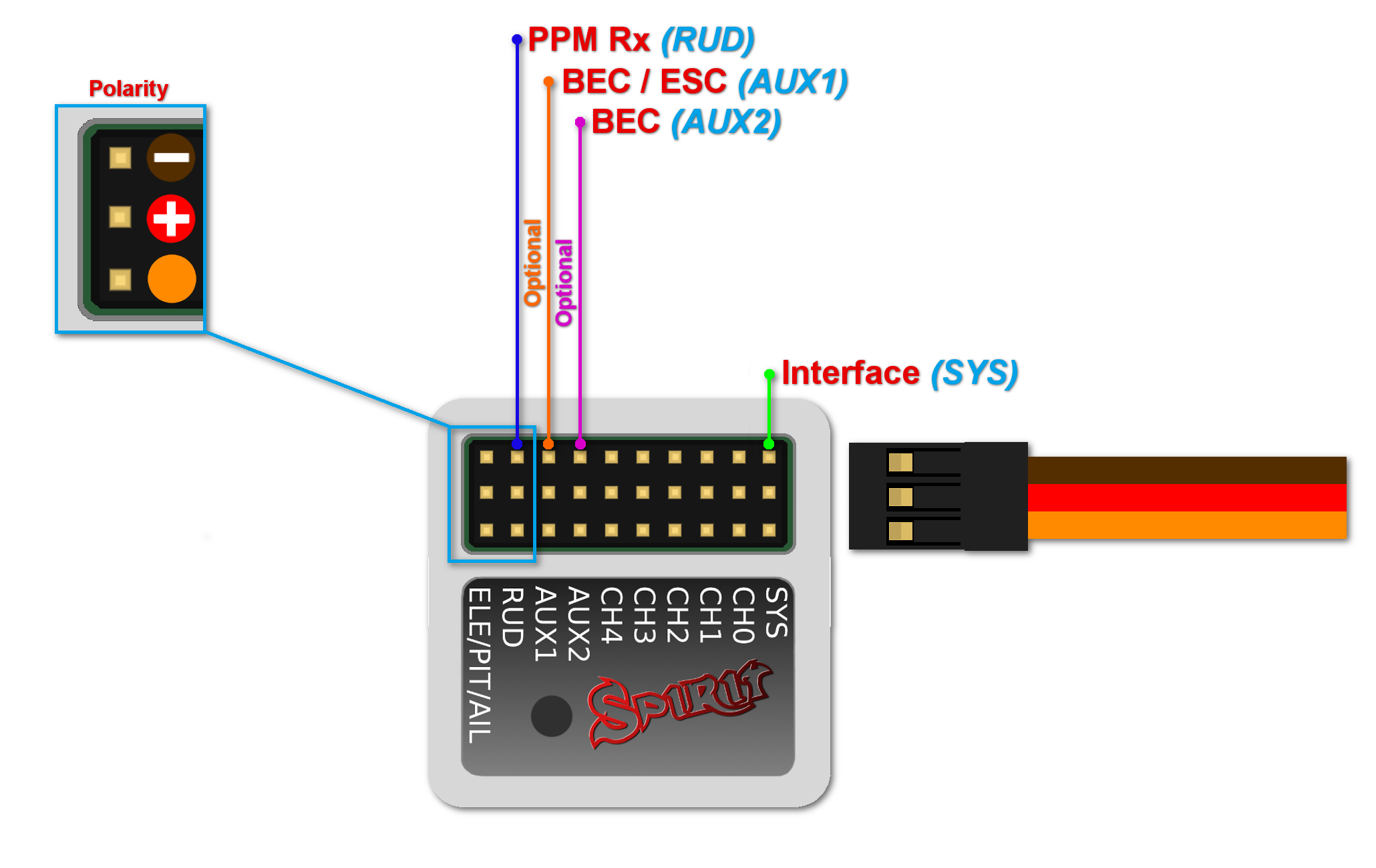
6 CONNECTION OF PPM RECEIVER
μSpirit – receiver type: PPM
Spirit – receiver type: PPM
Spirit Pro – receiver type: PPM
Connection to a BEC is optional. For models with standard size servos it is recommended to use dual power supply cables due to the increased power consumption. That means besides the communication cable, an additional power supply cable should be connected to the AUX port.
When using this type of receiver you can connect the throttle cable directly to the receiver. Alternatively, you can assign the throttle channel in the software and use the AUX as throttle output from the unit.
Never plug a connector for powering the unit to SYS or ELE/PIT/AIL ports.
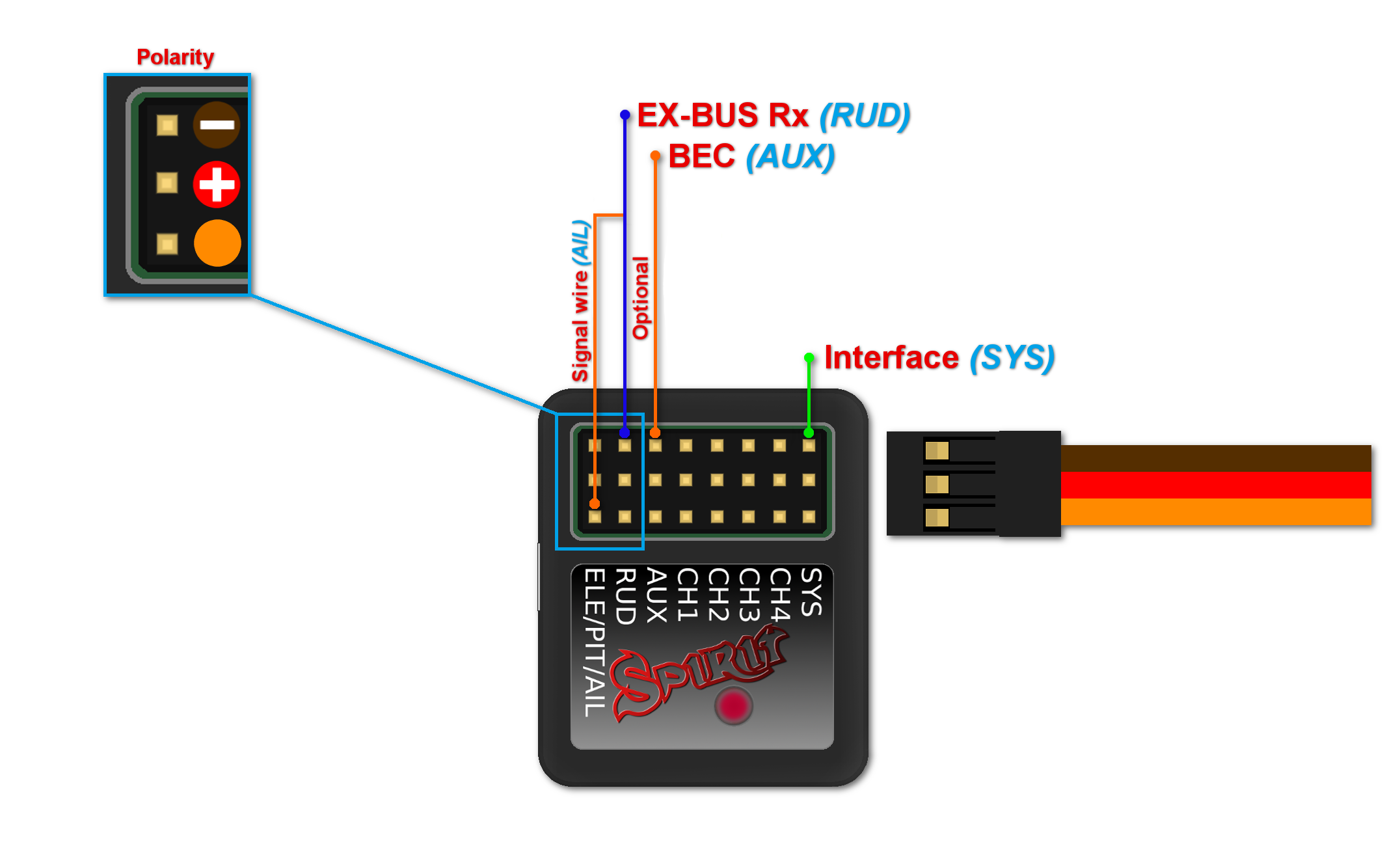
7 CONNECTION OF JETI EX BUS RECEIVER
μSpirit – receiver type: Jeti EX Bus
Spirit – receiver type: Jeti EX Bus
Spirit Pro – receiver type: Jeti EX Bus
Connection to a BEC is optional. For models with standard size servos it is recommended to use dual power supply cables due to the increased power consumption. That means besides the EX Bus cable, an additional power supply cable should be connected to the AUX port.
When using this type of receiver you can connect the throttle cable directly to the receiver. Alternatively, you can assign the throttle channel in the software and use the AUX as throttle output from the unit.
A special cable is needed to enable this communication. Signal wire (Orange) is connected to the AIL pin, while power wires (Red and Brown) are connected to the RUD port in the unit. For JETI REX receivers, end of the special cable is connected to the EX1 or EX2 (depending on the receiver configuration). For EX receivers, please use EXT port.
Never plug a connector for powering the unit to SYS or ELE/PIT/AIL ports.
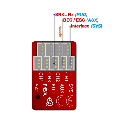
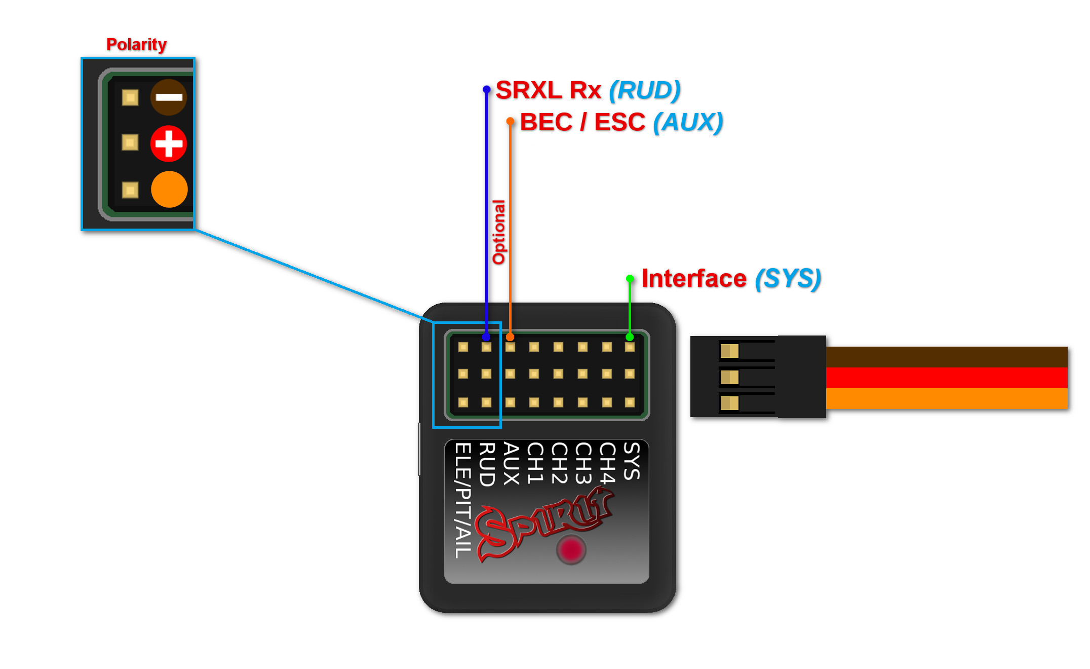
8 CONNECTION OF SRXL/SUMD RECEIVER
μSpirit – receiver type: SRXL/SUMD
Spirit – receiver type: SRXL/SUMD
Spirit Pro – receiver type: SRXL/SUMD
Connection to a BEC is optional. For models with standard size servos it is recommended to use dual power supply cables due to the increased power consumption. That means besides the communication cable, an additional power supply cable should be connected to the AUX port. This protocol family can work with a wide range of receivers. Thus you can use Multiplex SRXL, BeastX SRXL, Graupner SUMD, Jeti UDI, Spektrum SRXL and more.
When using this type of receiver you can connect the throttle cable directly to the receiver. Alternatively, you can assign the throttle channel in the software and use the AUX as throttle output from the unit.
Never plug a connector for powering the unit to SYS or ELE/PIT/AIL ports.
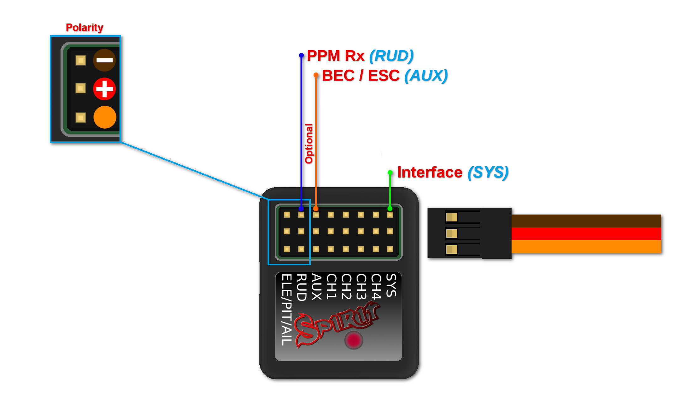
9 CONNECTOR ORIENTATION
9.1 μSpirit
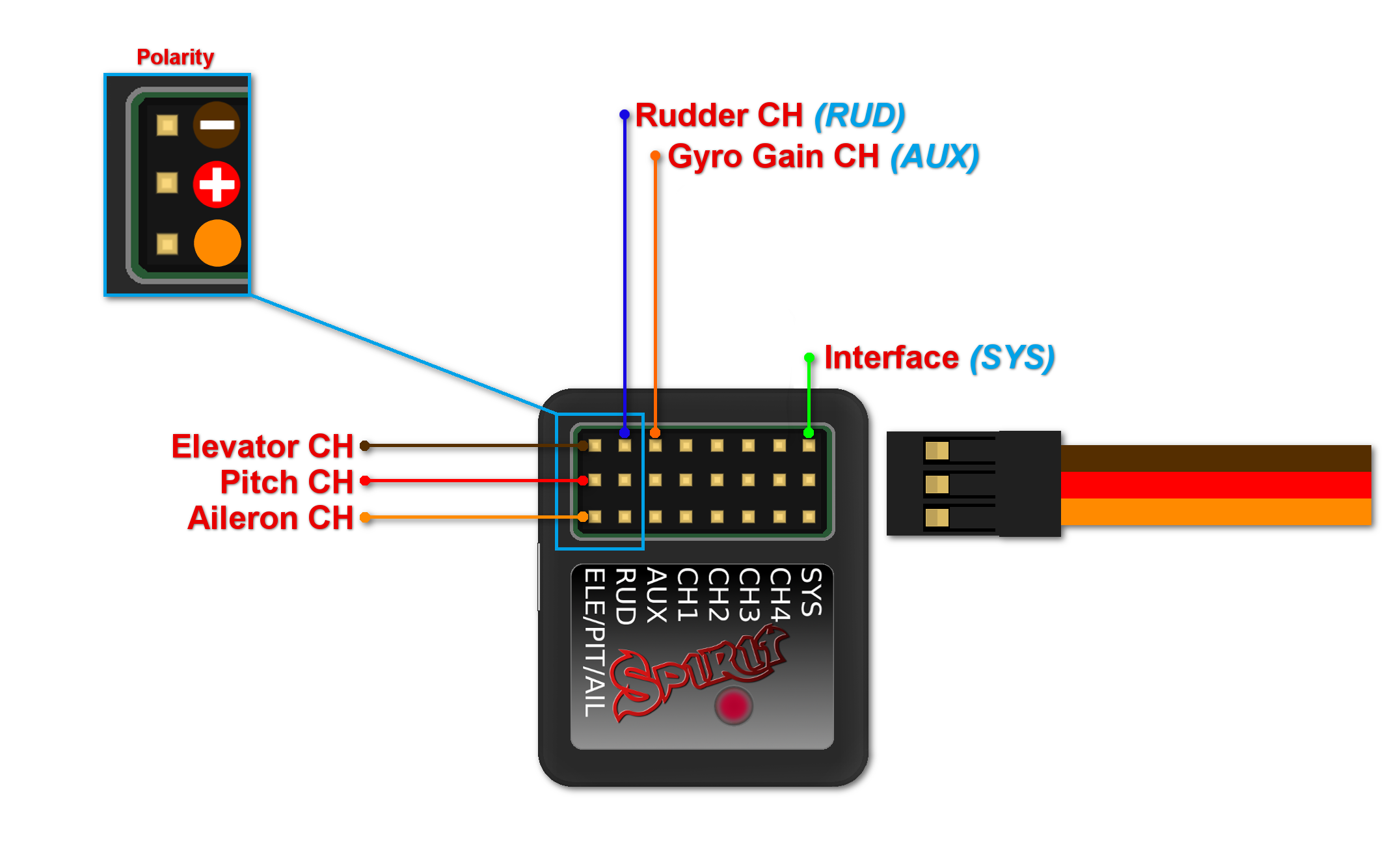
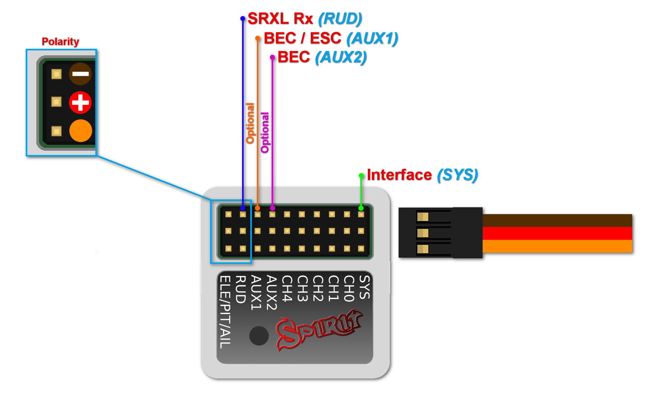
Pin layout of the JST-ZH(R) connectors is different from standard Servo connectors. BROWN (Middle) wire is GND pin. ORANGE wire is SIGNAL pin. RED wire is +5V (BEC voltage). By using JST-Servo cables you can connect a classic Servos and all Spirit peripherals to the μSpirit even with Servo connectors.
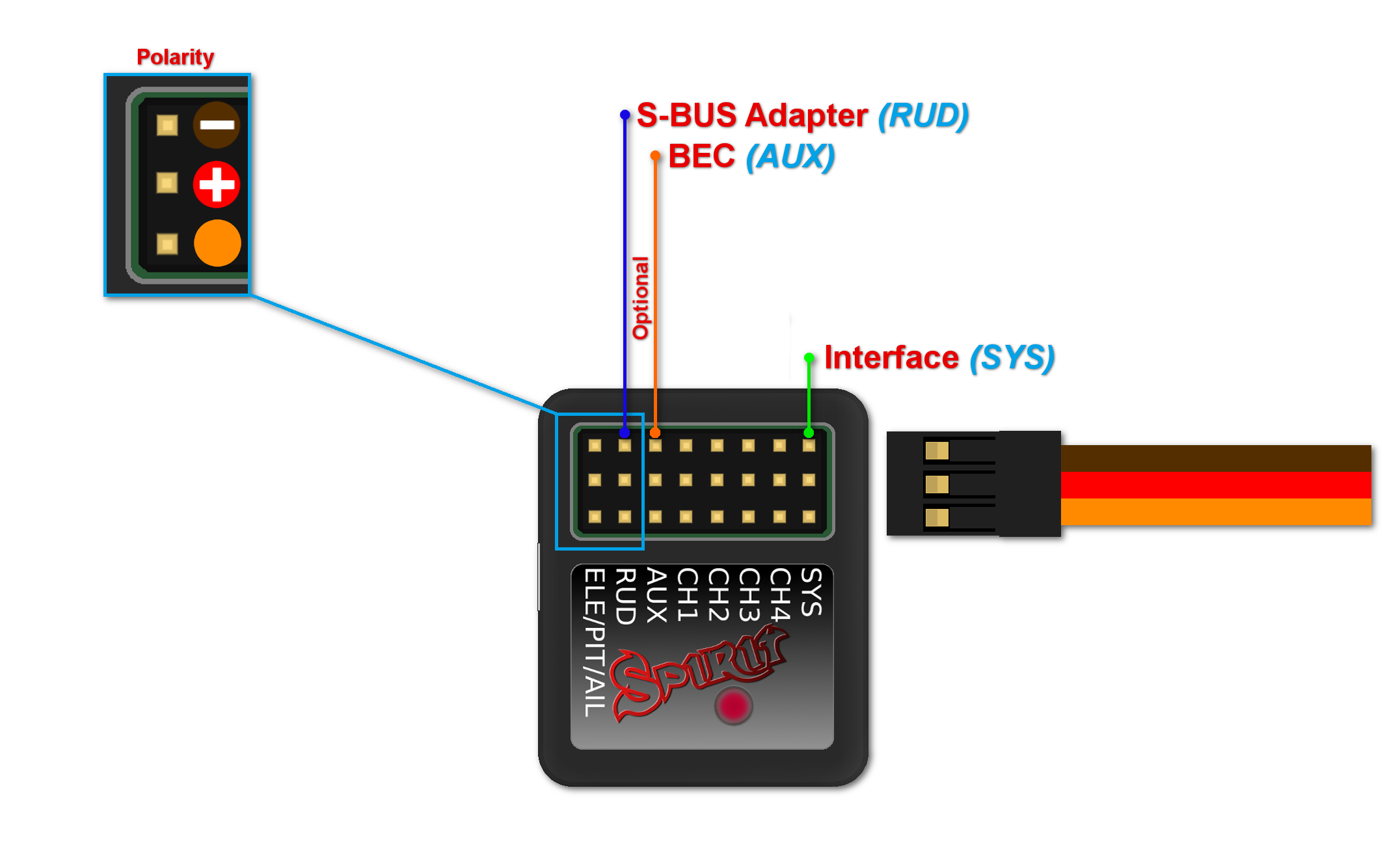
9.2 Spirit and Spirit Pro
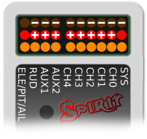
All cables connected to the unit must be oriented so that the signal wire (Lightest color wire) is closer to the connector pin label, towards the center of the unit. This orients the negative (darkest color wire) toward the edge of the unit.
