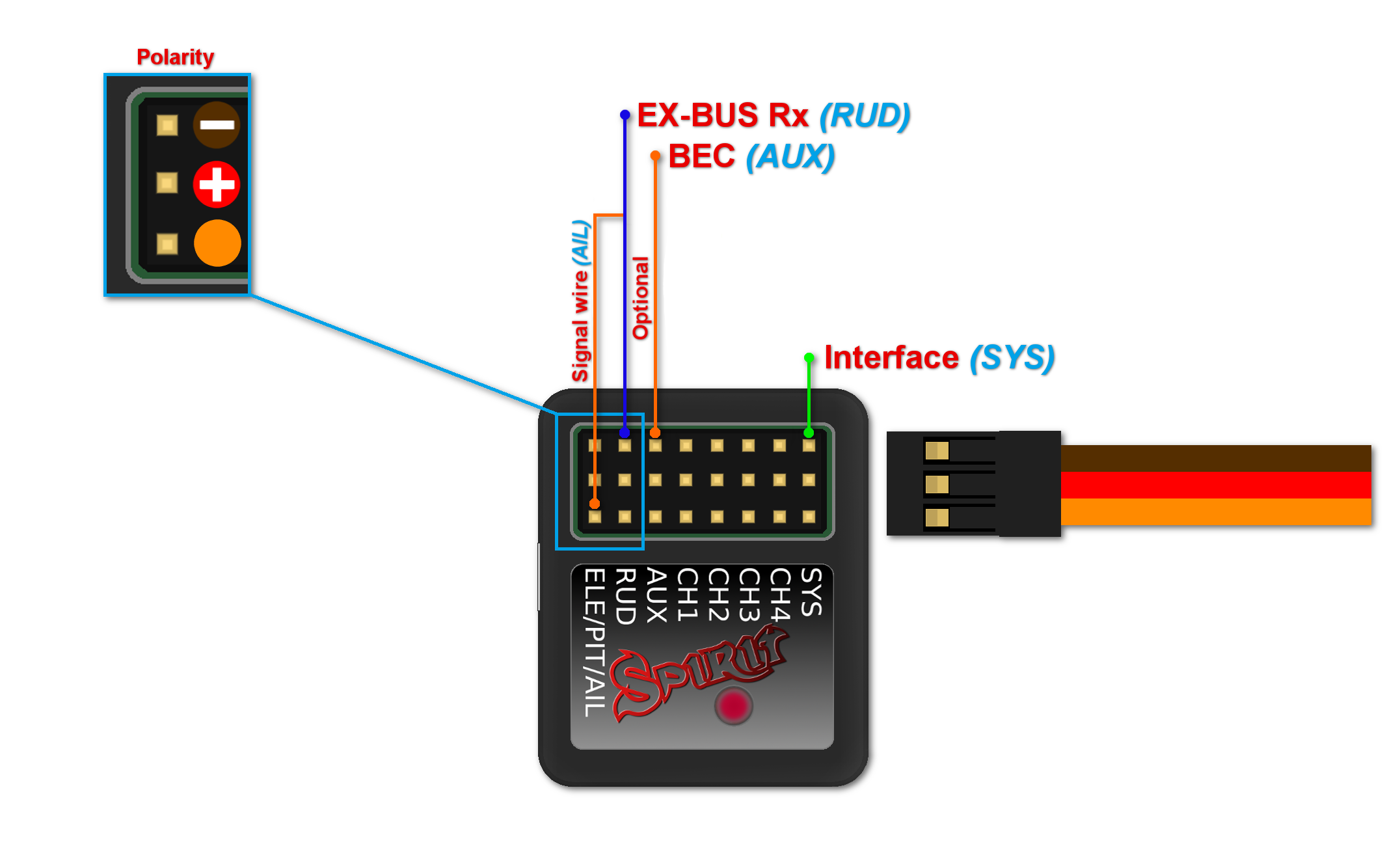
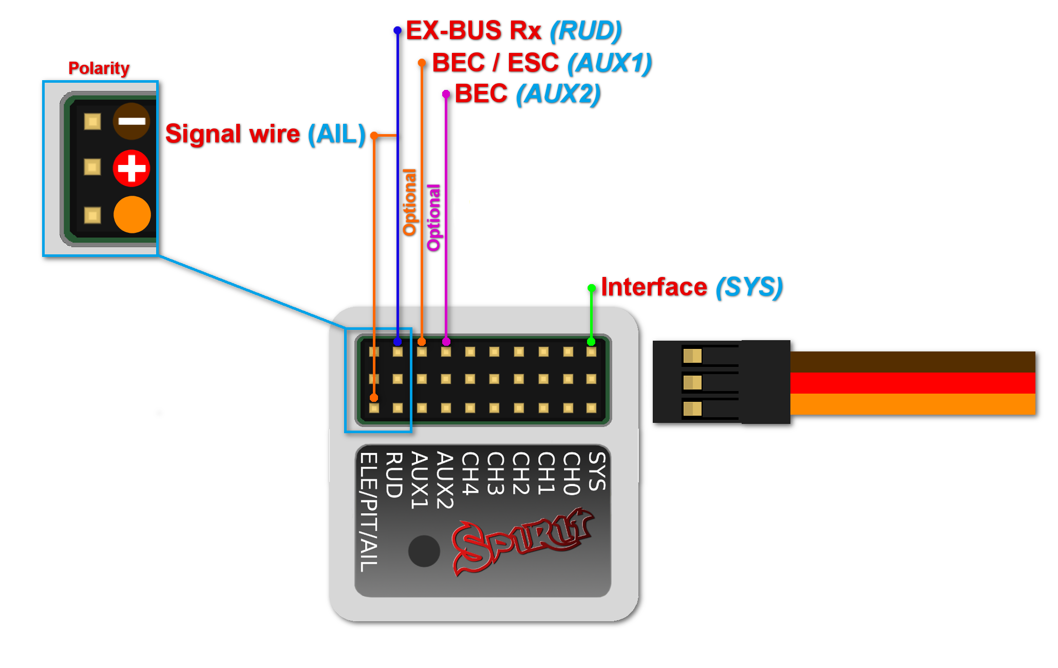
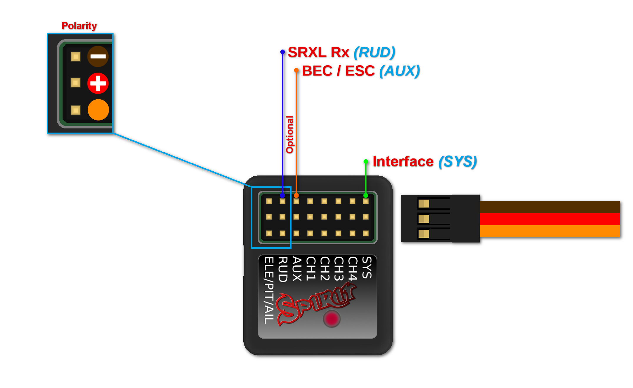
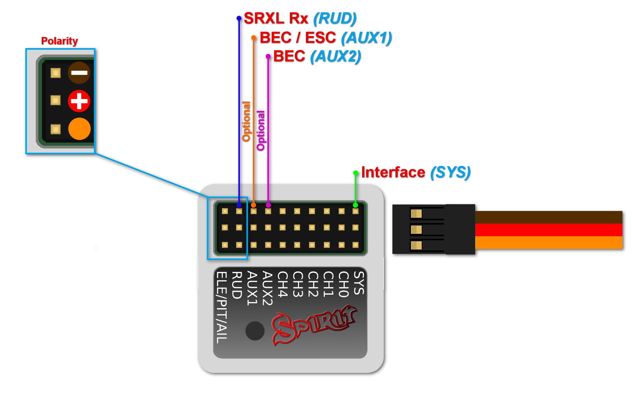
Verkabelung
Das Spirit kann als unabhängiger Kreisel, zur Stabilisierung und als Rettungsystem angeschlossen werden. Die Verkabelung der Einheit hängt vom eingesetzten Empfänger ab.
ACHTUNG
Das Spirit ist auf 1520μs Servo neutraler Impuls und 50 Hz Frequenz vorprogrammiert – bitte
vergewissern Sie sich, dass Sie die richtigen Servo- Parameter, wie vom Servohersteller spezifiziert,
ausgewählt haben.
Einige Stecker haben keine Standardabmessungen, diese könnten nach dem Einstecken in die
Einheit nebenstehende Stecker stören. Zur Lösung empfehlen wir, sie durch JR- oder Futaba-
Stecker zu ersetzen.
Stecken Sie niemals einen Stecker zur Stromversorgung der Einheit in SYS oder ELE/PIT/AIL
Schnittstellen oder Sie riskieren die Einheit zu beschädigen!
Contents
1 GYRO
Die R/C-Modelle können alle Eigenschaften und Möglichkeiten der Spirit-Einheit nutzen. Das Spirit wird das Modell in allen Achsen stabilisieren und weniger windanfällig machen. Bei richtigem Setup sollten die Flugeigenschaften stabiler sein, was Ihnen das Vertrauen gibt, auch die herausforderndsten Manöver auszuführen.
Nichtsdestotrotz können Sie die Stabilisierung auch vollständig deaktivieren, so dass die Steuerung gleich ist wie ohne das System. Dann kann es jederzeit wieder während Des Fluges aktiviert werden.
| Spirit |
| CH1 – 1tes Querruder / Höhenruder Servo |
| CH2 – Höhenruderservo |
| CH3 – 2tes Querruder / Höhenruderservo |
| CH4 – Seitenruderservo |
| Spirit Pro |
| CH1 – 1tes Querruder / Elevon servo |
| CH2 – Höhenruderservo |
| CH3 – 2tes Querruder / Elevonservo |
| CH4 – Seitenruderservo |
| CH0 – Aux (optionales Servo) |
ACHTUNG
Nürflüger (Delta) solten nur die Ausgänge CH1 und CH3 verwenden.
2 CONNECTION OF STANDARD RECEIVER (PWM)
Spirit – receiver type: PWM
Spirit Pro – receiver type: PWM
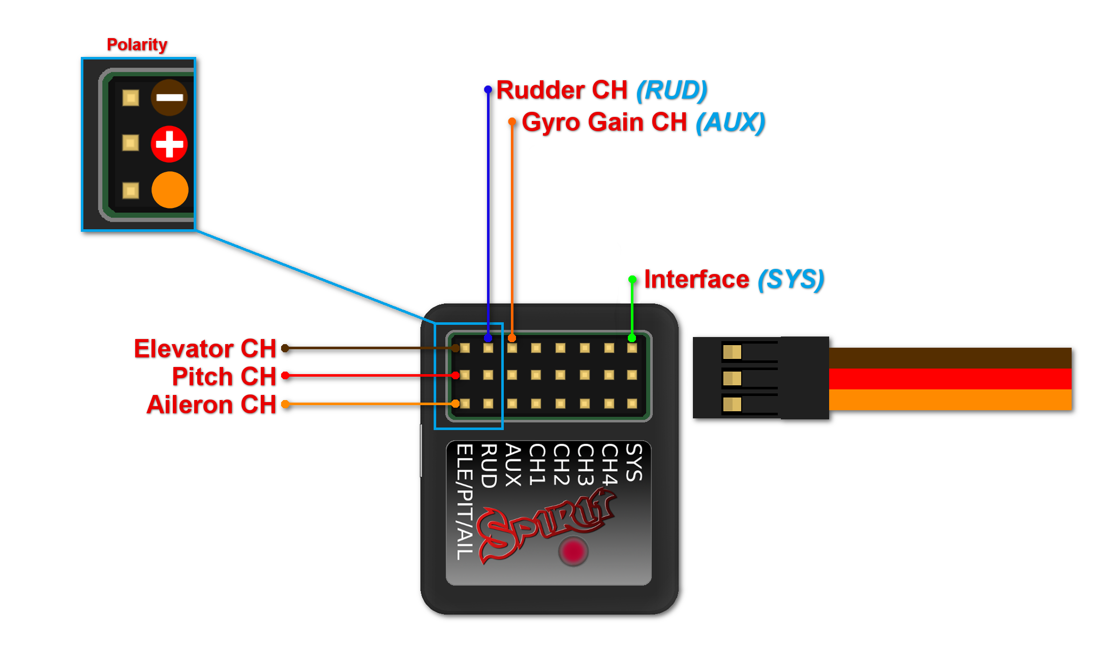
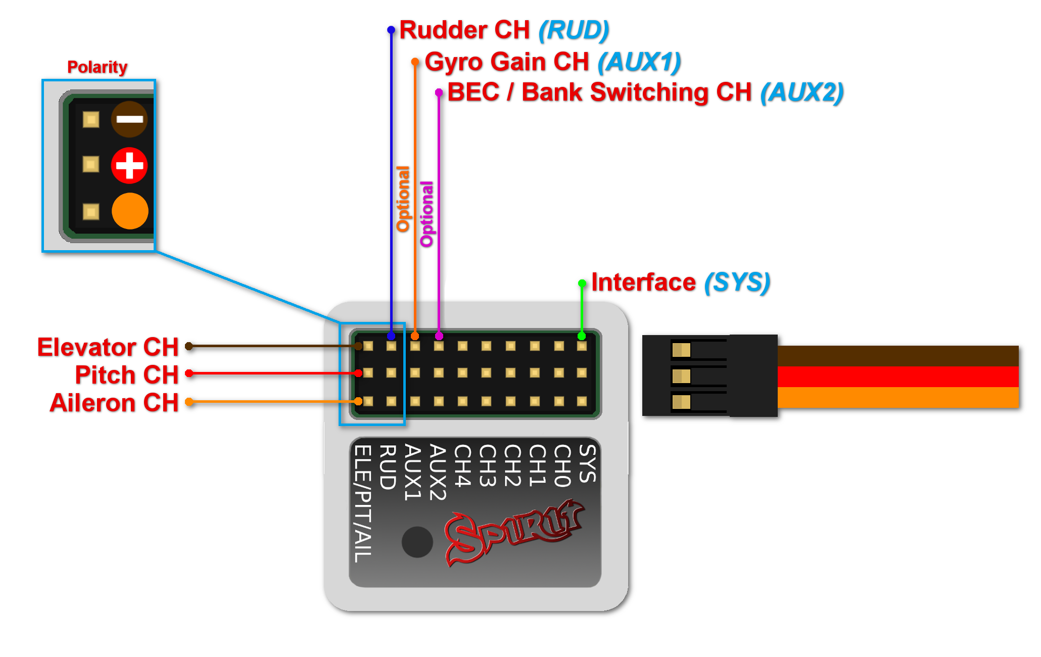
For standard receivers it is necessary to use two normal and one special cable. Three connectors from the special cable should be plugged into the receiver and the end of this cable to the unit.
The unit is powered by two cables from the receiver connected to AUX and RUD positions. The Throttle cable should be connected to the receiver as well.
The easiest way you can start connect RUD with Rudder output in the receiver. Then continue with AUX which should be connected to the Gyro Gain channel output. Next, connect the Aileron, Elevator and Pitch (Aileron 2) channels. If you are not sure whether you have the correct output or not, you can plug in one servo and power the unit to verify that your connection is correct. This can be repeated for each servo. The diagnostics tab is very helpful too.
Never plug a connector for powering the unit to SYS or ELE/PIT/AIL ports.
3 CONNECTION OF SPEKTRUM DSM2/X SATELLITE
Spirit – receiver type: Spektrum DSM2/X
Spirit Pro – receiver type: Spektrum DSM2/X
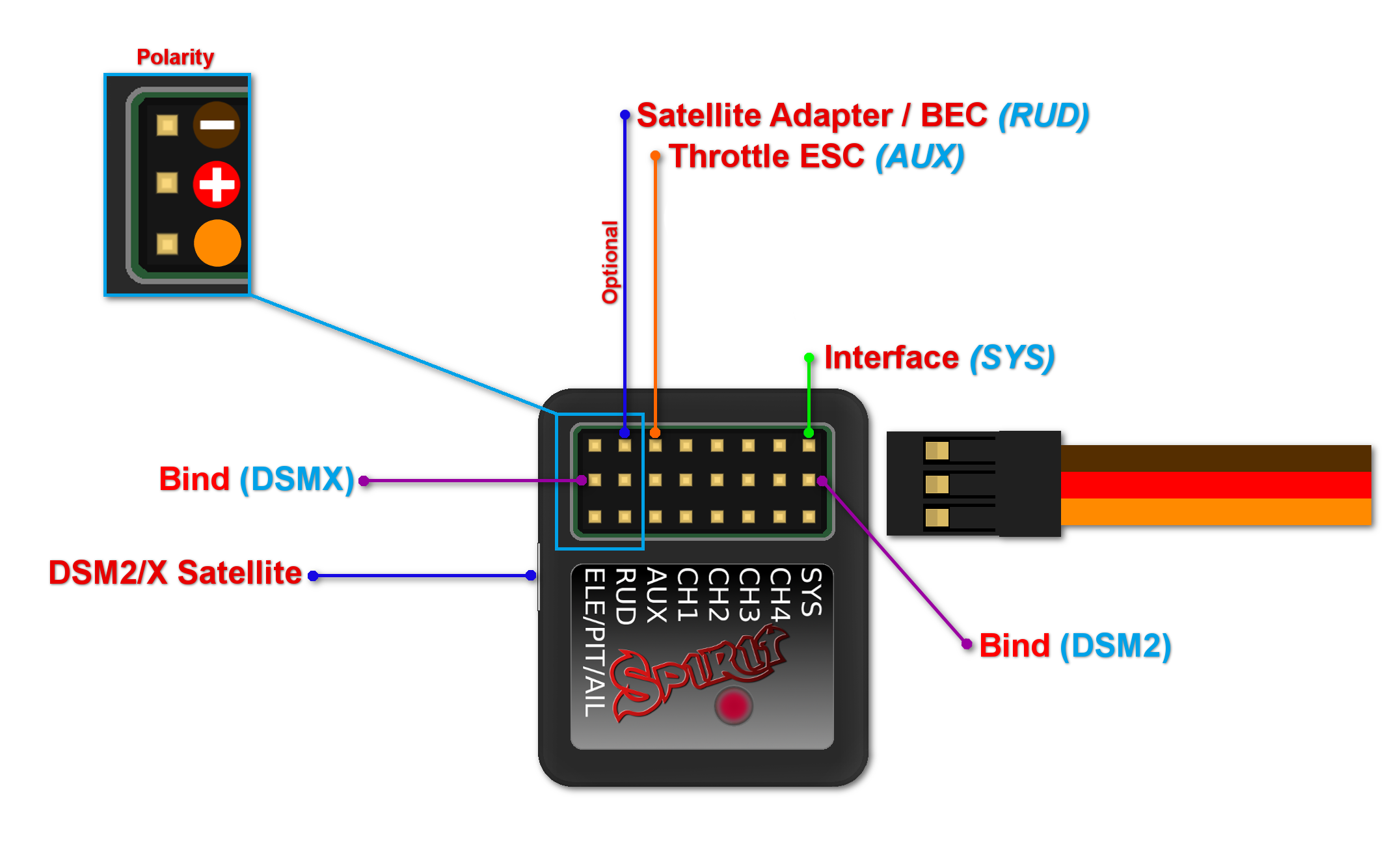
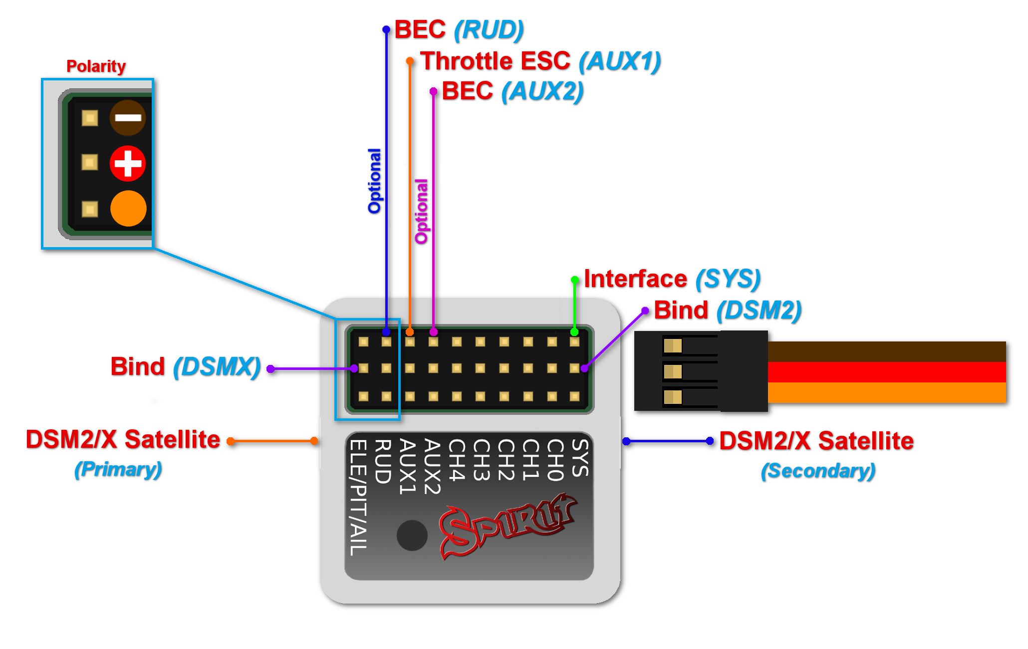
Connection to a BEC is optional. If the model is powered by an external BEC, this must be connected to the RUD port. Also the power lead from the ESCs internal BEC must be disconnected.
To bind the satellites, insert a bind plug in the SYS port for DSM2 satellites or the ELE/PIT/AIL port for DSMX satellites. Power cycling the Spirit start the bind process. Once successfully bound, the STATUS LED will go out and the satellite LED will come on.
If the second satellite fails to bind, swap the satellites and repeat the bind process.
Be sure Receiver type in the software is configured to Spektrum DSM2/X or else binding process will not work. Never plug a connector for powering the unit to SYS or ELE/PIT/AIL positions.
4 CONNECTION OF FUTABA S-BUS RECEIVER
Spirit – receiver type: Futaba S-BUS
Spirit Pro – receiver type: Futaba S-BUS
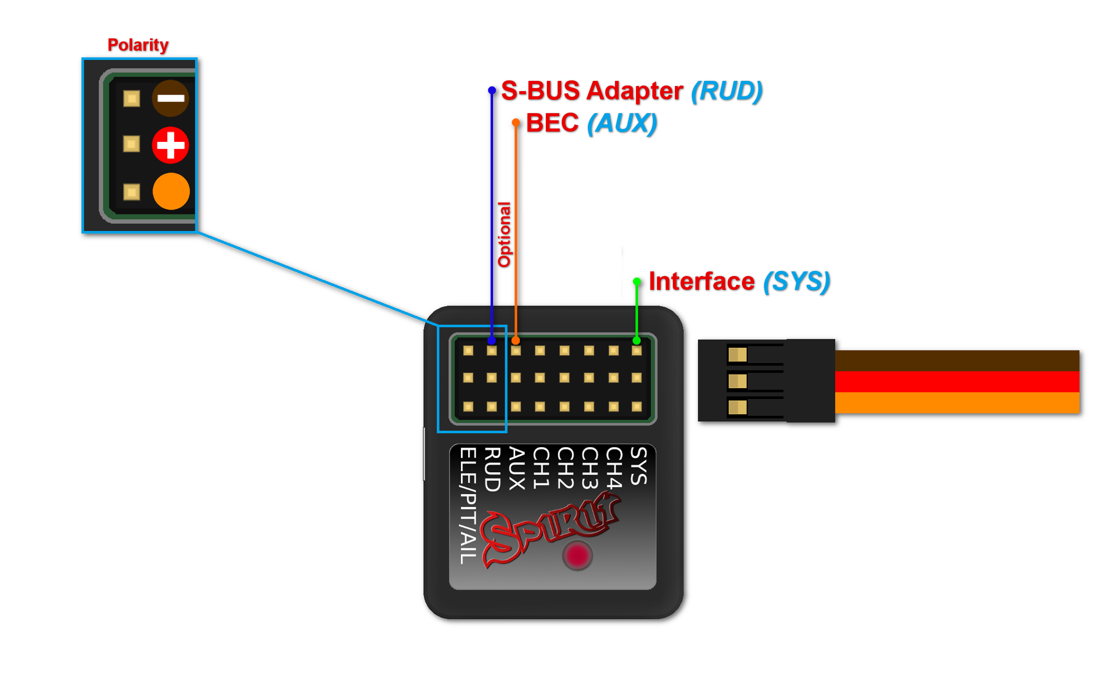
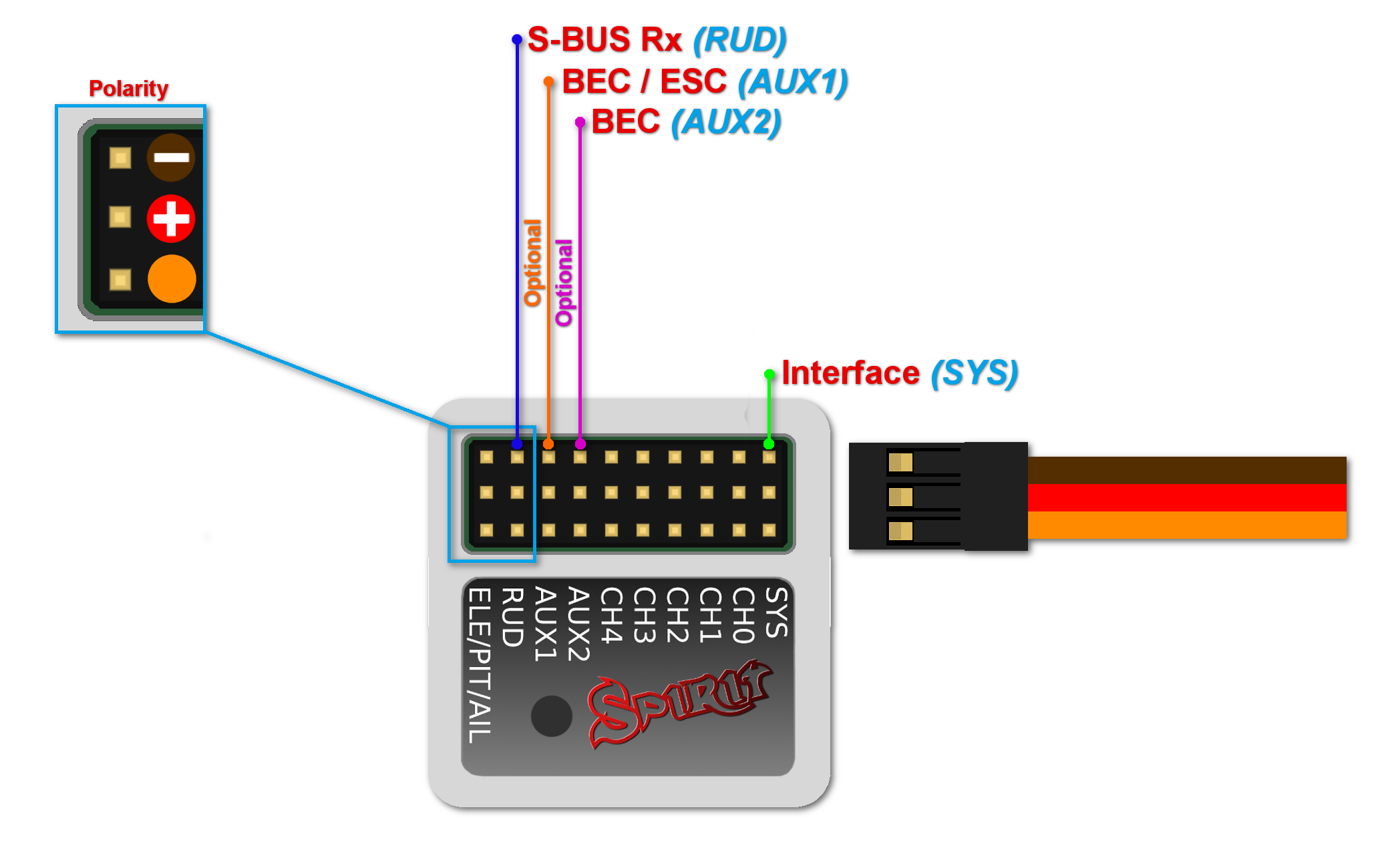
Connection to a BEC is optional. For models with standard size servos it is recommended to use dual power supply cables due to the increased power consumption. That means besides the S-BUS cable, an additional power supply cable should be connected to the AUX port.
When using this type of receiver you can connect the throttle cable directly to the receiver. Alternatively, you can assign the throttle channel in the software and use the AUX as throttle output from the unit.
Never plug a connector for powering the unit to SYS or ELE/PIT/AIL ports.
5 CONNECTION OF PPM RECEIVER
Spirit – receiver type: PPM
Spirit Pro – receiver type: PPM
NOTE
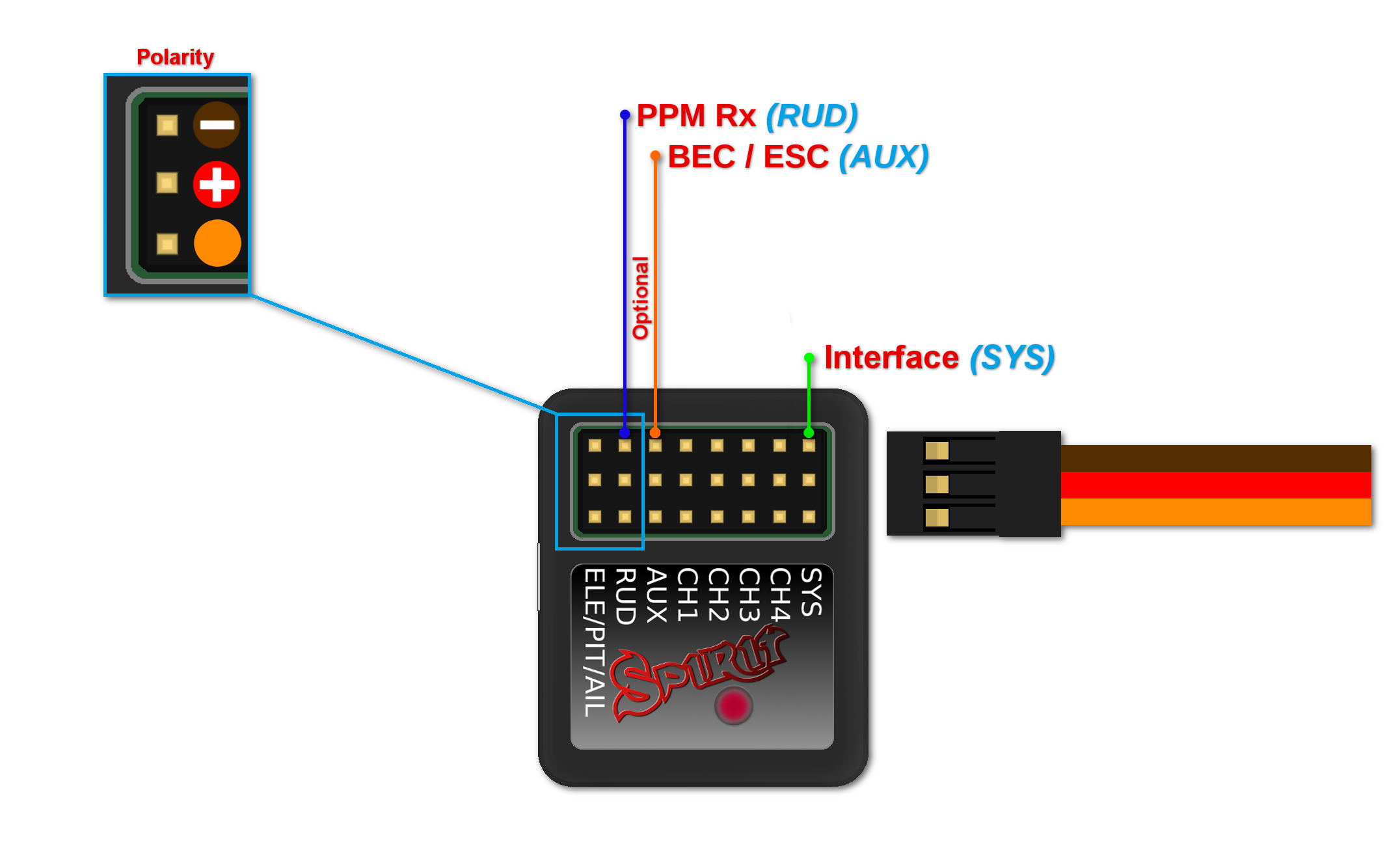
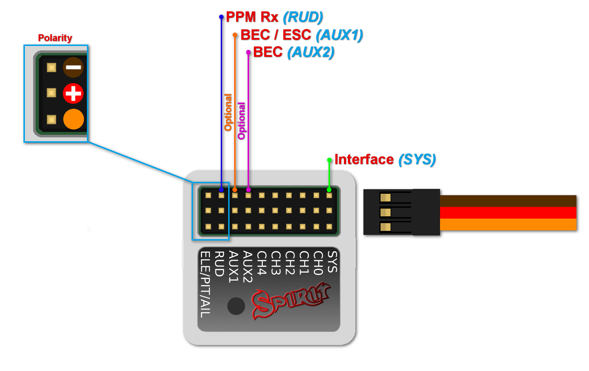
Connection to a BEC is optional. For models with standard size servos it is recommended to use dual power supply cables due to the increased power consumption. That means besides the communication cable, an additional power supply cable should be connected to the AUX port.
When using this type of receiver you can connect the throttle cable directly to the receiver. Alternatively, you can assign the throttle channel in the software and use the AUX as throttle output from the unit.
Never plug a connector for powering the unit to SYS or ELE/PIT/AIL ports.
6 CONNECTION OF JETI EX BUS RECEIVER
Spirit – receiver type: Jeti EX Bus
Spirit Pro – receiver type: Jeti EX Bus
NOTE
Connection to a BEC is optional. For models with standard size servos it is recommended to use dual power supply cables due to the increased power consumption. That means besides the EX Bus cable, an additional power supply cable should be connected to the AUX port.
When using this type of receiver you can connect the throttle cable directly to the receiver. Alternatively, you can assign the throttle channel in the software and use the AUX as throttle output from the unit.
A special cable is needed to enable this communication.
Never plug a connector for powering the unit to SYS or ELE/PIT/AIL ports.
7 CONNECTION OF SRXL/SUMD RECEIVER
Spirit – receiver type: SRXL/SUMD
Spirit Pro – receiver type: SRXL/SUMD
NOTE
Connection to a BEC is optional. For models with standard size servos it is recommended to use dual power supply cables due to the increased power consumption. That means besides the communication cable, an additional power supply cable should be connected to the AUX port.
This protocol family can work with a wide range of receivers.
Thus you can use Multiplex SRXL, BeastX SRXL, Graupner SUMD, Jeti UDI, Spektrum SRXL and more.
When using this type of receiver you can connect the throttle cable directly to the receiver. Alternatively, you can assign the throttle channel in the software and use the AUX as throttle output from the unit.
Never plug a connector for powering the unit to SYS or ELE/PIT/AIL ports.
8 CONNECTOR ORIENTATION
All cables connected to the unit must be oriented so that the signal wire (Lightest color wire) is closer to the connector pin label, towards the center of the unit. This orients the negative (darkest color wire) toward the edge of the unit.
