Nastavení
Konfigurace probíhá pomocí software, jenž kombinuje přímočarost s jednoduchostí, přičemž nabízí kompletní souhrn nastavitelných parametrů včetně pokročilých možností.
Konfigurační program nabízí průvodce nastavením. Výrazně ho doporučujeme použít, neboť usnadní celou konfiguraci a provede uživatele až k samotnému startu.
Contents
1 PROPOJENÍ S POČÍTAČEM
Předtím, než začnete samotnou konfiguraci a spustíte konfigurační software je nutné propojit systém Spirit s počítačem. Toto propojení umožňuje tzv. USB interface skládající se ze sériového převodníku a propojovacího kabelu. Po připojení převodníku do portu USB v počítači je v závislosti na daném operačním systému nutné nainstalovat ovladač (driver).
Aplikaci Spirit Aero je možné provozovat na systémech:
- Microsoft Windows
- Apple OS X
- GNU/Linux
- FreeBSD
V případě, že bude ovladač správně nainstalován, operační systém vytvoří nový virtuální COM port viditelný např. v software či správci zařízení
MICROSOFT WINDOWS
Nainstalujte ovladač pomocí instalátoru konfiguračního software jak bude uvedeno v následující kapitole.
APPLE MAC OS X
Pro správné fungování je velmi důležité stáhnout a nainstalovat ovladač z adresy:
http://spirit-system.com/dl/driver/SiLabsUSBDriverDisk.dmg
GNU/LINUX a FreeBSD
Není nutné nic doinstalovat.
1.1 WIFI-LINK
Program Spirit Aero lze spojit s jednotkou také pomocí Wifi modulu. Jedná se o tzv. Spirit Wifi-Link. Odpadne tak nutnost používat USB interface a konfiguraci je možné provádět bezdrátově. Jak modul připojit a nastavit je popsáno v jeho příručce, kterou lze stáhnout zde
2 PROPOJENÍ S JEDNOTKOU
Pokud již máte USB interface v počítači zapojen, je potřeba, aby byl druhý konec kabelu připojen do zdířky SYS v jednotce Spirit. Pro navázání spojení připojte napájení jednotky. Pro napájení jednotky lze využít výstup z BEC, přijímače nebo baterie. Běžně se využívají dvě propojky kanálu RUD a AUX, kde prostřední vodič musí být kladný potenciál napájecího napětí, tedy plus (jednotka podporuje napětí 3 – 15V).
Napájení nepřipojujte nikdy na pozici SYS či ELE/PIT/AIL.
3 INSTALACE KONFIGURAČNÍHO SOFTWARE
Stáhněte software a postupujte následovně v závislosti na operačním systému, který používáte. Je volně dostupný na webu Spirit System http://aero.spirit-system.com//.
MICROSOFT WINDOWS
Spusťte stažený software - instalátor a postupujte instalací. Pokud ještě nebyl ovladač nainstalován, zvolte ho v instalátoru k instalaci. Instalátor vás provede až do stavu, kdy je vše v počítači připraveno pro první spuštění konfiguračního software. Spustitelný soubor konfiguračního software se bude nacházet v seznamu programů či na ploše jako „Spirit Aero“.
APPLE MAC OS X
Nainstalujte software poklepáním na stažený soubor DMG. Přesuňte jeho obsah do adresáře Aplikace. Konfigurační software lze poté spustit z Aplikace poklepáním na „Spirit-Aero“.
GNU/LINUX a FreeBSD
Extrahujte všechny soubory ze staženého archivu, např. v domovském adresáři. Konfigurační software lze poté spustit z nově vytvořeného adresáře souborem „settings.sh“.
4 SPUŠTĚNÍ KONFIGURAČNÍHO SOFTWARE
Jsou-li předchozí pokyny splněny a jednotka je již pod napětím a inicializovaná (LED svítí), lze spustit software na vašem počítači.
Spusťte aplikaci Spirit Aero např. z plochy nebo adresáře, kde byla provedena instalace.
UPOZORNĚNÍ
Konfigurační software spouštíme vždy až po inicializaci jednotky! Kdykoliv je tedy jednotka propojená a inicializovaná (svítí status LED), lze provádět libovolné nastavení. Konfigurace během letu se z bezpečnostních důvodů výrazně nedoporučuje.
PROBLÉMY VE WINDOWS
Pokud konfigurační software nedetekuje COM port k interface, spusťte jej jako Správce – pravé tlačítko myši na settings.exe. V některých případech se po instalaci ovladače přiřadí k interface (zařízení Silabs) vysoké číslo COM portu. Z tohoto důvodu je nutné ve správci zařízení tomuto portu přiřadit číslo menší (např. COM1 – COM4). Na přenosných počítačích je také vhodné vypnout uspávání USB zařízení.
5 POUŽITÍ SOFTWARE
Po spuštění a úspěšném propojení by měly být všechny možnosti přístupné, v opačném případě zkuste buďto zvolit jiné komunikační zařízení (Zařízení) nebo software ukončit, odpojit jednotku z napájení a celý postup opakovat.
Ujistěte se, že je software spuštěn až po inicializaci jednotky.
5.1 ZÁLOŽKA SPOJENÍ
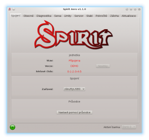
Tato záložka indikuje současný stav spojení, informuje o aktuální verzi firmware, zobrazuje sériové číslo jednotky a nebo umožňuje změnu komunikačního zařízení. Mimo to nabízí průvodce provotním nastavením.
Doporučujeme tohoto průvodce využít, neboť vás provede od základního nastavení až k prvnímu startu.
5.2 ZÁLOŽKA OBECNÉ
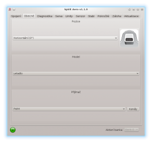
V případě, že jste již nastavili jednotku pomocí průvodce, lze zde provádět dodatečné úpravy. Všechny hodnoty zde, budou takové, jaké jste zvolili v průvodci a obráceně.
UPOZORNĚNÍ
Kdykoliv jsou jednotlivé parametry změněny, nastavená hodnota se ihned uplatní. Dokud není nastavení uloženo, je po odpojení napájení konfigurace uvedena do předchozího stavu, viz záložka Záloha – to platí během celé konfigurace.
Pozice
Zvolte pozici v jaké je jednotka připevněna k modelu, viz kapitola 3. Montáž.
Model
Select the model type.
In case that the model is equipped with 3-4 servos, please select Plane.
For Flying Wing (Delta), please select Flying Wing.
Přijímač
Zvolte typ přijímače, který budete používat:
PWM – klasický přijímač.
PPM – signály přes jeden propojovací kablík.
Spektrum DSM2/DSMX – satelit s podporou DSM2/DSMX.
Futaba S-BUS – přijímač připojený přes sběrnici S-BUS.
Jeti EX Bus – přijímač připojený přes sběrnici EX Bus (integrace s JETI model).
SRXL/SUMD – přijímač připojený přes sběrnici SRXL, SUMD, UDI.
Kanály
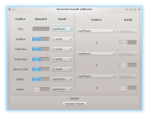
Po klepnutí na tlačítko je otevřeno okno, kde je možné přiřadit libovolně kanály přijímače na dané funkce. V závislosti na typu přijímače je možné přiřazovat více či méně kanálů. Pamatujte, že je nežádoucí přiřadit stejný kanál na dvě či více funkcí.
Po přiřazení kanálu funkce Plyn je aktivován výstup z jednotky na pozici AUX. Po přiřazení kanálu funkce Banky je aktivována možnost přepínání Bank, viz kapitola 5.6.
When a channel for Global Gain function is unassigned, it is possible to configure
global gain directly through this software in Sensor tab. The unassigned channel
could be used in another way, e.g. for Bank switching.
Failsafe
U přijímačů PPM, Futaba S-BUS, Spektrum DSM2/X, Jeti EX Bus, SRXL/SUMD lze nastavit tzv. Failsafe přímo v jednotce. Hodnoty všech kanálů se po kliknutí na tlačítko Nastavit Failsafe uloží do jednotky. Pokud je signál přijímače ztracen na dobu 1 sekundy a déle, použijí se uložené hodnoty.
U ostatních typů přijímačů je režim Failsafe naprogramován ve vysílači či přijímači.
Realtime ladění
Přiřazením parametru (P) je možné provádět nastavení přímo pomocí vysílače. Zvolený parametr je možné pohodlně nastavit na základě výchylky kanálu pomocí řídícího prvku (např. potenciometrem). Pro konfiguraci tedy není nutné spojení s konfiguračním programem, ale postačí běžný vysílač. Změna výchylky kanálu ihned mění hodnotu parametru. Maximální výchylka zvoleného kanálu nastaví nejvyšší možnou hodnotu parametru, minimální výchylka pak tu nejnižší hodnotu. Realtime ladění parametrů má nejvyšší prioritu. To znamená, že nebude použita hodnota nastavená v profilu ani v bankách.
Tato funkcionalita je aktivní pokud není spuštěn konfigurační program, aby se zabránilo případné kolizi. Jakmile je program odpojen, je hodnota zvoleného parametru nastavena na základě výchylky kanálu. Pokud je program znovu spuštěn, zobrazí se hodnota naposledy nastavené výchylkou kanálu. Avšak při spuštěném programu již znovu platí předchozí pravidla (výchylka kanálu nebude mít vliv).
Je možné nastavovat simultánně až 3 různé parametry či funkce.
Pokud je nastavena funkce (F), je aktivní, když je hodnota rovna 1. Funkce Analýza vibrací umožňuje měření vibrací během letu. Tato funkce je dále popsána v kapitole Diagnostika.
Po doladění parametru doporučujeme připojit program, nastavení uložit do paměti jednotky a následně ladění parametru vypnout.
UPOZORNĚNÍ
Ladění doporučujeme provádět vždy s největší opatrností, aby nedošlo ke ztrátě kontroly nad modelem!
5.3 ZÁLOŽKA DIAGNOSTIKA
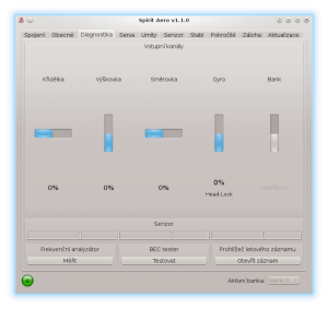
Pokud je nastavení v předchozí záložce hotovo, je nutné odpovídajícím způsobem provést mírné korekce v konfiguraci vysílače. Každý vysílač je odlišný a jeho středové impulzy všech kanálu nejsou nikdy naprosto stejné. Dokonce i s rostoucím opotřebením či působením okolních vlivů se můžou tyto středy mírně pohybovat. Dalším faktorem je maximální a minimální hodnota každého kanálu. Také zde mohou být větší odchylky. Proto jednotka Spirit umožňuje přesně tyto středy a rozsahy zobrazit a na základě toho lze výstup všech vysílačů sjednotit.
NOTE
For proper operation of the unit, it is necessary that movement of each
channel correspond with the bars. Direction of the movement must be same
as well.
Secondly it is necessary to check the values of aileron, elevator, pitch and rudder channels. These channels must be centered at approximately 0%. The unit automatically detects the neutral position during each initialization. Do not use subtrim or trim functions on your transmitter for these channels, as the Spirit unit will consider these as an input command.
Ensure all subtrims and trims are zeroed. It is also recommended to set the maximum and minimum values.
It is also recommended to set the maximum and minimum values. Test the minimum and maximum throws for all channels, if these values are not equal to -100% and 100% in the diagnostic tab it is necessary to adjust your transmitter endpoints to correct this.
After these adjustments, everything should be configured with regards to the transmitter. If some channels oscillate around the center, it may mean wear of the transmitter potentiometers. This can be compensated for by increasing stick deadband in the Advanced tab. (Covered later)
If the values in the aileron, elevator, or rudder channels are shown in bold, the system is recognizing a command to move/rotate the axes.
To determine Global Gain and gyro mode you can check Gyro bar in the Diagnostic tab. Following modes are available:
- N – Normal (Rate)
- HL – Head Lock (will hold direction)
- HF – Head Lock with active Function. (Covered in the Stabi tab)
SPECTRUM ANALYSER
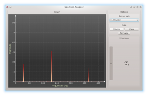
The Spectrum analyser is a tool for measuring the amount of vibrations on your model. It is a diagnostic tool designed to determine which rotating part is causing a problem. With this information you can easily identify and fix any problems with your model.
To check condition of the model you can see "Vibrations" bar. This indicate general vibration amplitude in selected axis.
It is possible to measure vibrations in three separate axes:
- X - elevator axis
- Y - aileron axis
- Z - rudder axis
- In-Flight - flight vibration player
The live graph shows frequencies for the currently selected axis. This enables you to see both the frequency and magnitude of the vibration on the selected axis.
Vibrations are transmitted to each axes dependent on several, various factors. Frequencies and magnitude are dependent on the model construction. Generally, the vibrations are the highest on Y axis (aileron) but we recommend you check all axes each time you are doing measurement. However vibrations should not exceed 50% for all axes at any time. In the case vibrations are at 90% or more, the model has an issue that needs to be rectified. Should the magnitude exceed 90% on any of the given axes, it is recommended to fix whatever issue is causing these extreme vibrations before flying the model. Even though Spirit unit is highly resistant to vibrations, these could cause unwanted interactions with the Spirit unit and could also cause mechanical failure of the model. Such high vibrations can cause Loctite to fail and other mechanical parts to break.
Vibration levels:
- Vibrations up to 50% - vibrations at a normal and acceptable level
- Vibrations between 50% and 90% - raised vibration levels
- Vibrations exceeding 90% - extreme vibration levels
As well as overall vibration levels not exceeding 50%, any specific frequency (peak) should not exceed 50%. Anything above this level should be cause for concern and requires further investigation.
For comparing the graphs, you can use the Freeze button. The current live graph is displayed and the graph captured using the Freeze button is saved and will be displayed as subgraph. This graph can be deleted with the Clear button.
It is possible to save the Spectrum analyser graphs. Using the To image button, the current graph will be saved as an image.
The Spectrum analyser is able to detect the vibration frequencies up to 500Hz (rotating parts at speeds up to 30,000 RPM).
Measurement procedure
- Remove a propellers from the model or block it from movement.
- Place the model on a suitable, soft surface (e.g. grass).
- Run the Spectrum analyser (this also freezes all servos).
- Spin up the motor to the usual flight RPM.
- Switch between the X, Y and Z axes, saving an image of each.
- Check vibrations in all axes.
- Stop the motor.
Recognizing vibrations
To recognize which component or part is causing abnormal vibrations it is necessary to determine the speed of the highest peaks. Usually it is the motor, it's shaft and bearings.
In order to find out which part of the model is causing the unwanted vibrations, move cursor to the peak and check the head speed (RPM).
Most excessive vibrations are usually motor related as it is the only one rotating part.
Once you identify which part of the model is causing the unwanted vibrations, you can gradually remove components of the suspect assembly, repeating the measurement process until the vibration disappears. Once the vibration levels have dropped to an acceptable level, you have found the suspect component and can replace it.
Measuring with propeller installed carries some safety concerns and will also show increased levels of vibration.
In-Flight - vibration analysis from flight
This feature allows you to record vibration spectrum from any moment of the flight. By selected channel you can tell the unit when the spectrum should be taken. The spectrum can be later viewer in the Spirit Aero software with the In-Flight option in the Diagnostic/Spectrum analyzer. Saved vibration spectrum will be stored until unit will lost the power. Saved record is rewritten on repeated activation.
For vibration measurement in the flight set the Special function in the General/Channels. Assign function F: Vibration analysis with axis you want to measure. Then select a channel which will be used for activation of the function.
As soon as the value is equal to 1 the vibration spectrum is saved. The record is saved exactly at the moment when function will change it's state from 0 to 1.
During flight it is enough to change state of selected switch of your transmitter (for example 2-state switch). After landing you can connect unit with the software and open the Vibration analyzer (select In-Flight axis to display the spectrum).
BEC TESTER
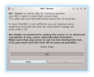
The tester is used for determining whether your power supply for the unit, receiver and servos is sufficient. The purpose is to achieve the biggest current spike and verify that your supply voltage will not drop under the safe level.
Click the Start button to start the test. After 20 seconds it should be finished.
If you will observe any issue, then your power supply is insufficient and should not be used. In this case power supply with higher current rating should used.
LOG VIEWER
The log is used to record events during flight. If a problem occurs and the reason isn't immediately known or evident, checking the log can help in identifying the issue.
It works in such a way that it records various events from the time the unit is powered on. If an event occurred you can see this in the log, reporting to the log is done every 10sec. When you click the Open log button you can see the current flight log which contains all the events from the last flight. When the power is disconnected, the log is cleared.
In the case of a major problem occurring during the flight ![]() , the log is then saved permanently to the unit's memory and remains there until such time as the log is opened.
If there is a saved log in memory, the user is advised with the message “Log from previous flight is available!” and the log from the flight when the problem occurred is opened. For example, when a signal is lost or the power supply failed you can find this in the log. The log from the first flight where the major problem occurred is always saved. If this is not opened, then it will not be overwritten with a newer one. In this state, the user is also notified by different cyclic pitch pump during the initialization process - elevator servo will change it's movement direction.
, the log is then saved permanently to the unit's memory and remains there until such time as the log is opened.
If there is a saved log in memory, the user is advised with the message “Log from previous flight is available!” and the log from the flight when the problem occurred is opened. For example, when a signal is lost or the power supply failed you can find this in the log. The log from the first flight where the major problem occurred is always saved. If this is not opened, then it will not be overwritten with a newer one. In this state, the user is also notified by different cyclic pitch pump during the initialization process - elevator servo will change it's movement direction.
The log can contain the following events:
- The model is in good condition. The unit did not recognize any problems.
-
- Sensor calibration was successful.
-
![]() Aileron, Elevator, Rudder Limit Reached:
Aileron, Elevator, Rudder Limit Reached:
- Some servo reached its configured limit. When this event occurs before or after a flight it is not a problem. If you see this during flight it indicates that the model achieved it's maximum configured deflection for the control elements/servos. Usually it is not an issue, but if you will notice that the model is unable to rotate fast enough, then the configured range in the Servo tab is too small.
-
- Received frame is unusable and will be ignored. In the most cases it does not present any problem. If the event is occuring often, then connection between receiver can be wrong or there is excess noise. Verify quality of the link and check the cable between unit and receiver.
-
- Signal lost suddenly. This problem should not occur at any time and must be resolved before the next flight. There could be a problem with the receiver and/or transmitter antennas. It could be a faulty receiver cable or the connection between the unit and receiver. In some cases signal loss can happen because of interference that is coming from a radio tower.
-
- The main loop was delayed. This can happen when wiring is incorrect or there is abnormal electrical noise interference with the unit, for example, from a BEC. If using the configuration software it could mean the link to the Spirit FBL unit is slower than it should be.
-
- Power supply voltage is lower than 2.9V. This mean you have to use a BEC that is capable of handling higher loads. In rare cases it could be faulty connections in cables.
-
- Vibration level achieved the level that is not normal and can affect integrity of the model. During hard acrobatic maneuvers the event can occur more frequently.
-
All reviewed logs are saved as PDF files into Documents directory.
5.4 SERVOS TAB
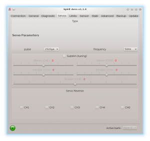
This tab is used for servo configuration, care should be taken to ensure correct frequencies are used and that the directions are set correctly.
Type
In this section, set the values for neutral pulse and frequency according to your servo manufacturer specifications.
For analog servos the frequency is usually a maximum of 60Hz.
Subtrim (tuning)
By ticking the item Subtrim (tuning) the unit will be switched into a special mode where you can set the servo neutral position. In addition, gyro will be disabled.
Servos can easily be adjusted at this time, e.g. by arrows.
Set all servos so that their arms are at the center as close as possible. At the same time the control elements (aileron, elevator, rudder) should be at the center position as well.
In most cases, it is also necessary for servo arms to be perpendicular to the main shaft. All servos, i.e., CH1, CH2, CH3 and CH4, are set separately on individual sliders. CH1 and CH3 are the aileron servos. CH2 controls the elevator and CH4 controls the rudder.
Once set up, un-tick the Subtrim (tuning) check box to turn off this special mode.
After exiting the special mode, gyro will work again.
Servo reverse
This allows you to choose which servos should have their direction of motion reversed. After this settings the model should react correctly to the sticks movement.
This parameter is the most important!
5.5 LIMITS TAB
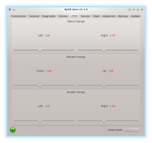
This tab affects limits and servo travel ranges.
Aileron, Elevator, Rudder range
Sets the minimum and maximum deflection of the servos.
We recommend setting these values for both directions to the maximum
allowed range by the manufacturer of the model. If range is too small, it will not allow you to perform fast rotations.
Do not exceed allowed limit for your model.
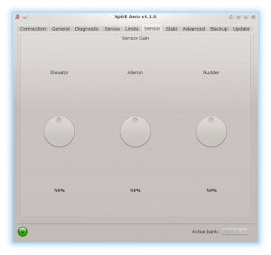
5.6 SENSOR TAB
This tab is the last important part of the settings which must be configured.
Global Gain – This parameter is enabled only in case of unassigned Gyro gain channel. It replaces function of Gyro gain from the transmitter, so you can directly set the value in the software.
Sensor Gain
The rotary dial adjusts the gyro sensitivity for aileron, elevator and rudder axes.
Aileron, Elevator, Rudder – The higher the value is, the higher the accuracy within the control loop. The default value is preconfigured to 50% gain. If oscillation is observed on a certain axis, decrease the gain.
Global Gain in the software or in your transmitter can be programmed in this way:
- Head-Lock mode: 1% to 100%
- Normal (Rate) or a special function: -100% to 0%
Negative Global Gain can be used to activate the rescue or the stabilisation modes – check the Stabi tab.
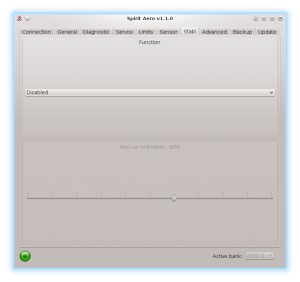
5.7 STABI TAB
The Spirit unit offers you the options of model stabilization and rescue mode. The stabilization function, once activated, will recover the model to a horizontal or ascending position without any other input from the pilot, this can be used as a “bail-out” feature when trying new maneuvers and can help with the learning process.
Rescue mode complements the normal operation of the Spirit unit. If activated, the model will recover to a configured inclination and can start with ascending as per the settings. This function can be used any time when the pilot loses orientation or control of the model.
The Spirit unit allows you to assign a stabilization or rescue mode using the gyro gain channel. 0 - 100% gain in the transmitter is always heading lock gyro mode and with -100 – 0% gain, you are able to activate stabilization or rescue mode. This means that instead of normal (rate) mode, it will stay in heading hold gyro mode, plus rescue/stabilization is activated. So, while rescue/stabilization mode is activated, a gyro gain of -70% is considered as 70%. This behavior can be also observed in the Diagnostic tab.
Some transmitters have a gyro range of 0 to 100% where 50% is the middle - zero gain (e.g. Spektrum DX6i). Others use a range of -100% and 100%, where 0% is the middle.
Function
Here is where you select which mode should be activated at negative Global Gains.
Disabled - Normal (Rate) gyro mode.
Rescue (Normal) - Recovers the model to an upright horizontal position – skids always to the ground. This recovery mode is great for the beginners.
Rescue (Acro) - Recovers the model to a horizontal position, inverted or upright, whichever is closer at the time of activation. For intermediatte and advanced pilots that are flying acrobatic manouvers.
Stabilization (Normal) – stabilization mode - gears always to the ground. This mode is good for learning the basics such as hovering and slow transitions. Model is always pushed to the horizontal position.
Stabilization (Acro) – stabilization mode - inverted or upright, whichever is closer at the time of activation. This mode is used for learning the basics of acrobatic maneuvers. If the sticks are in the center, the model has tendency for returning to the horizontal position.
If using these modes, be sure your model is initialized on a flat surface, not tilted to any side. Do not tilt the model for more than 5 seconds after initialization. It can be initialized in normal or inverted position.
The rescue mode is very demanding on the BEC. Be sure your BEC can handle such peak loads. In case it is is not sufficient your model could crash! Never exceed angles recommended by manufacturer of the model, else the mechanics can be damaged during the flight!
Rescue inclination
This determines inclination of the model that will be maintained during rescue activation.
100% means the maximum inclination (angle) of the model.
With 0% model will recover to the horizontal position.
Direction control rate
This specifies the rate of controlling direction for the stabilization mode.
Low values are well suited for beginners. Higher values are more appropriate for Acrobatics learning.
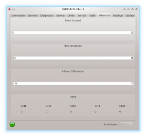
5.8 ADVANCED TAB
This tab is for more advanced configuration of the Spirit unit. It is recommended that you fully understand these parameters before adjusting them. These parameters rather depend on preferences of the pilot.
Feed forward
This parameter is used to set amount of direct feel between your sticks and
your model. The higher the value, the more aggressive the model will feel and the faster the model will react to the stick movements.
If the value is very high, bounce-back effect can occur when a stick is released quickly. It will also affect rotation speed in all axes similarly to Dual Rate.
If the model feels disconnected and there is a lag between stick inputs and
the model, try increasing this value.
Stick deadband
Determines the area, around center stick, where the system does not recognize any stick movement. If channel readings are inprecise the value should be increased. This can be verified in the Diagnostics tab. This parameter does not replace the Exponential function.
Aileron Differential
In case that direction during aileron rotation is not held precisely increase the value.
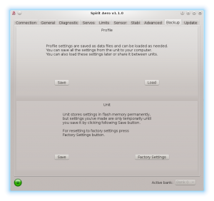
5.9 BACKUP TAB
Here, you can save the settings to your Spirit unit before powering off, you can also save the settings to your computer here, Should you need to reload them at a later date.
Profile
This section allows you to Save and Load complete settings of the unit to a specified file. If you have more than one of the same model, it is not necessary to carry out a complete setup again, just load the stored settings easily with the Load button.
Unit
Any changes to the configuration can be saved at any time to the internal flash memory of the unit.
To put all settings to a factory defaults, click Factory Settings.
Remember to save the settings each time you want to store the settings permanently. You must press the Save button. Otherwise, the changes will be lost after the Spirit FBL unit is turned off.
Bank Switching
In case that the Bank Switching is enabled, you can save the settings from single bank or even all banks. To see the differences between Banks you can use Bank Comparison feature.
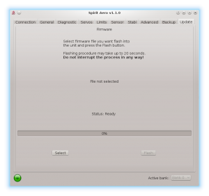
5.10 UPDATE TAB
If you want to update the firmware, you can do so in this tab.
Firmware
First select the data file containing the firmware (*.4df) – Select button.Once the file is selected, press the Flash button. The upgrade progress will be displayed here. After completion, a confirmation dialog box should indicate a successful update.
Then, unplug the unit from its power source.
Upon the next start it will load with the newly flashed firmware.
Configuration of the unit is not changed, so you do not need to save/load it.
You can get firmware from: aero.spirit-system.com.
6 BANK SWITCHING
This functionality allows you to switch between saved settings during a flight. Switching is done through the transmitter, so that channel's value is changed. This mean that a Bank can store one unique settings. The unit is able to store 3 different banks.
With a transmitter you are able to use a three position switch to switch freely between banks.
Bank switching is disabled by default, so you can decide whether it is useful in your application. You have to activate it by the assignment of Bank function in the General/Channels window. Generally, it is assigned to channel 7.
Bank 0 – active in range of lower third (impulse under 1400μs).
Bank 1 – active in range of mid third (impulse between 1400μs to 1640μs).
Bank 2 – active in range of upper third (impulse above 1640μs).
Initial settings for Bank 1 and Bank 2 are equal to Bank 0. Bank 0 allow you to configure all parameters, while Bank 1, 2 does not allow to set main parameters. For safety, Bank 1 and 2 does not allow you to set any main parameters.
The Bank switching is great for switching between sensor gains for low or high flying speed, for slow acro or demanding maneuvers. Alternatively it can be used just for tuning your settings.
If the software is connected with the unit then bank switching via the transmitter is disabled. Then, Bank switching is performed using the software in bottom part of the window. When a bank is switched using the software it is necessary to save your settings to the unit before you switch Banks, or your settings will be returned to the previous (unchanged) state.
7 SOFTWARE KEYBOARD CONTROL
For fast and easy configuration we have implemented keyboard controls in the software.
| Shortcut | Function |
|---|---|
| F1 to F10 | Switch between tabs. |
| ESC | Exit current window. |
| CTRL + S | Save settings to the unit. |
| CTRL + P | Save profile to your computer. |
| CTRL + L | Load profile from your computer to the unit. |
| CTRL + W | Connection settings for the Wifi-Link module. |
| Numpad 0, 1, 2 | Switch between banks. |
| Tab | Switch between parameters. |
| Space | Select parameter / option |
| Arrows | Increase / Decrease value. |
| Page Up / Page Down | Increase / Decrease value by tens. |
| Home | Set the lowest value. |
| End | Set the highest value. |
